Carl Goldberg GBGA1045 User Manual
Page 10
10
3.
Make a mark 1/4” inboard from the center of the
stab and 1/8” back from the top of the bevel.
Transfer this mark to the other side of the stab.
Using a 1/8” drill, drill the hole for the control
horn.
4.
Install the 6-32 x 3-1/2”” bolt, nylon washer,
nylon nut, and tighten down.
Install the pushrod fitting on the end.
Repeat for the other elevator.
5.
Hinge the elevators in place using the same
method we did on the ailerons and rudder.
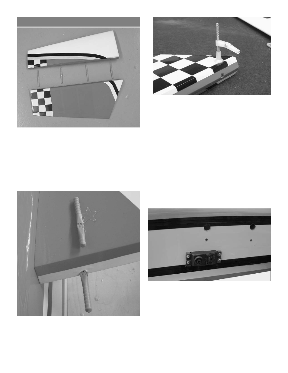
Stabilizer and Elevator Installation
1.
Collect the following parts:
(2) stab halves
(2) elevator halves
(8) hinges
(2) 6-32 x 3-1/2” control horn bolts
(2) nylon nuts
(2) nylon washers
(2) adjustable control horns
2.
The two inboard hinges will have to be cut off
1/2” because of the rear aluminum tube.
Trial fit the elevators to the stab and make
sure all hinges will go in half way.
6.
It is easier to mount the elevator servos now
before mounting the stab.
Connect a 12” extension to each servo and
mount in the holes with the output arm forward.
- GBGQ1296 (12 pages)
- GBGA1079 (25 pages)
- GPMA0963 Cub (33 pages)
- GBGA1023 (12 pages)
- GBGA1069 (29 pages)
- GPMA1956 Eagle 2 ARF (40 pages)
- GPMA0955 EAGLE 2 (59 pages)
- GBGA1080 (9 pages)
- GBGA1046 (21 pages)
- GBGA1040 (16 pages)
- GBGA0040 (40 pages)
- GBGA1082 (10 pages)
- GBGA0055 (44 pages)
- GBGA1041 (20 pages)
- GBGA1070 (17 pages)
- GBGA1078 (23 pages)
- GBGA0050 (26 pages)
- GPMA1940 EP Falcon ARF (16 pages)
- GBGA0057 (60 pages)
- GPMA1960 Gentle Lady Glider ARF (16 pages)
- GPMA0960 Gentle Lady (21 pages)
- GBGA1091 (15 pages)
- GBGA1042 (9 pages)
- GBGA1019 (13 pages)
- GBGA1072 (14 pages)
- GBGA1075 (18 pages)
- GPMP1020 Mini Hold'em Electric Cradle (2 pages)
- GBGP0105 (10 pages)
- GBGA1090 (16 pages)
- GBGA1064 (24 pages)
- GBGA1088 (30 pages)
- GPMA1926 Monster Pitts Electric ARF (17 pages)
- GBGA1058 (9 pages)
- GBGA1087 (16 pages)
- GBGA1092 (24 pages)
- GBGA1085 (19 pages)
- GPMA1993 Skylark 70 Sport ARF (18 pages)
- GPMA1959 Sophisticated Lady Glider ARF (20 pages)
- GBGA0059 (32 pages)
- GPMA1967 Sr. Falcon ARF (21 pages)
- GBGA1089 (19 pages)
- GBGA1067 (19 pages)
- GBGA0067 (39 pages)
- GBGP0108 (4 pages)