Wiring diagrams – Braeburn 3300 User Manual
Page 12
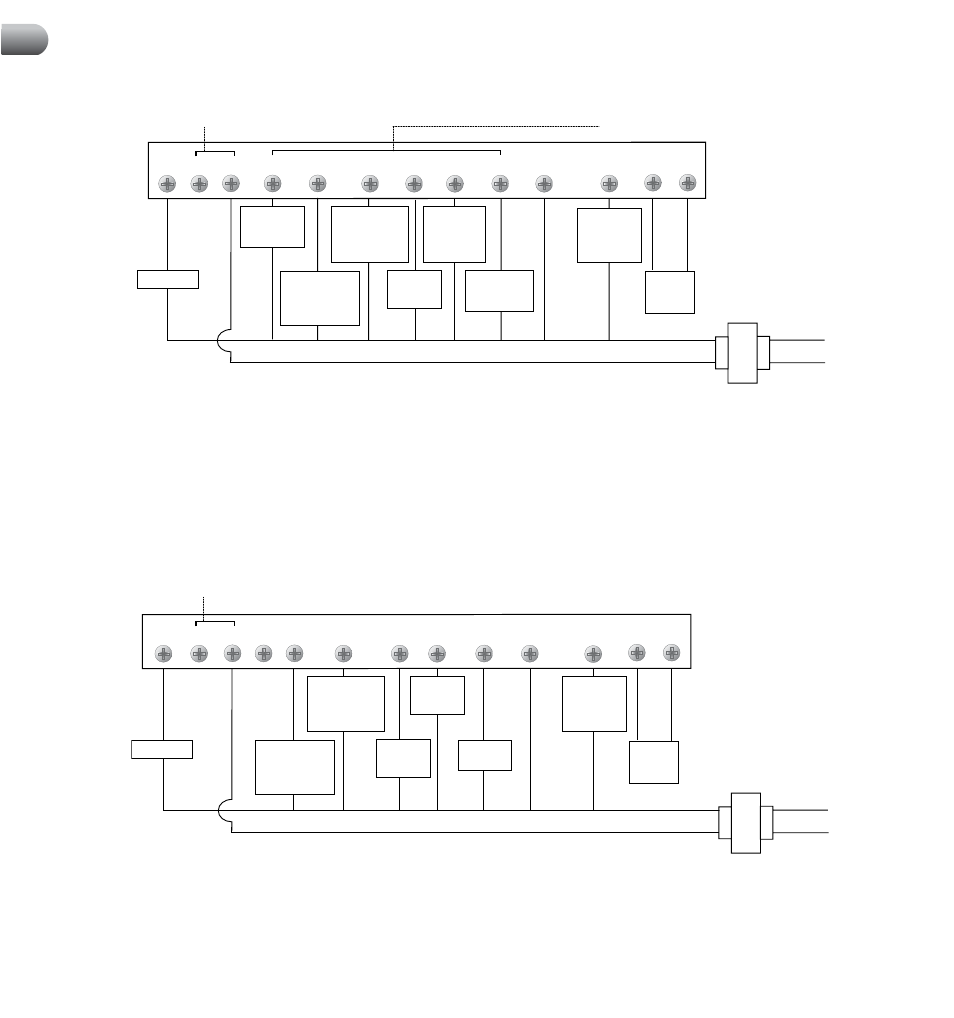
Emergency
Heat Control
(See NOTE 4)
1st Stage
Compressor
Control
2nd Stage
Compressor
Control
(NOTE 2)
2nd Stage
Heat Control
(NOTE 2)
Fan Control
Remote
Sensor
(NOTE 6)
Reversing Valve
(Active in
Cooling - See
NOTE 3)
System
Malfunction
Indicator
(NOTE 7)
(See NOTE 5 for
Jumper Instructions)
Transformer Common (See NOTE 1)
Neutral
120 VAC
Hot
24 VAC
Reversing Valve
(Active in
Heating - See
NOTE 3)
One and Two Stage Heat Pump Systems
G
Rc
Rh
W2
B
O
Y1
W1/E/W3 C
L
S1
S2
Y2
Factory Installed Jumper
Remote
Sensor
(NOTE 3)
Factory Installed Jumper
Aux Heat
Control
1st Stage
Compressor
Control
2nd Stage
Compressor
Control
Fan Control
Reversing Valve
(Active in
Cooling - See
NOTE 2)
System
Malfunction
Indicator
(NOTE 4)
Transformer Common (See NOTE 1)
Neutral
120 VAC
Hot
24 VAC
Reversing Valve
(Active in
Heating - See
NOTE 2)
Three Stage Heat Pump Systems
G
Rc
Rh
W2
B
O
Y1
W1/E/W3 C
L
S1
S2
Y2
NOTES:
1. Transformer Common connection not required for battery-only operation of thermostat.
2. Second Stage Control connections not used for single stage heating or cooling systems.
3. For units requiring reversing valve to be energized during heating, connect reversing
valve to B terminal. For units requiring reversing valve to be energized during cooling,
connect reversing valve to O terminal.
4. Required for units with 2 stage heat only.
5. For 2 stage heat units not having a separate Emergency Heat Terminal, add installer
supplied jumper.
6. Remote Sensor Terminals can be either for Outdoor or Indoor Remote
Sensor depending on installer settings.
7. If L Terminal is used, 24VAC common (C terminal)
must be connected.
NOTES:
1. Transformer Common connection not required for battery-only operation of thermostat.
2. For units requiring reversing valve to be energized during heating, connect reversing
valve to B terminal. For units requiring reversing valve to be energized during cooling,
connect reversing valve to O terminal.
3. Remote Sensor Terminals can be either for
Outdoor or Indoor Remote Sensor depending on installer settings.
4. If L Terminal is used,
24VAC common (C terminal) must be connected.
9
Wiring Diagrams
cont.