Wiring diagrams – Braeburn 3300 User Manual
Page 11
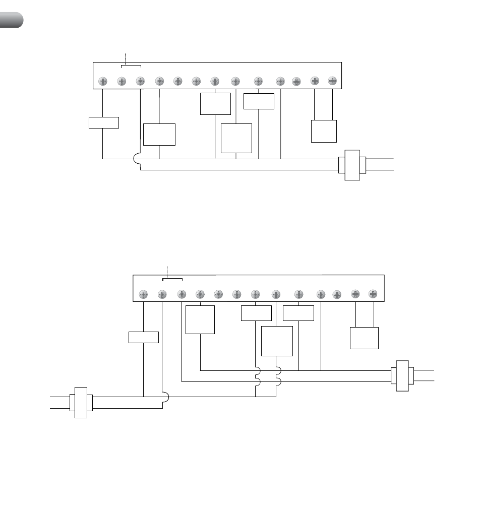
Factory Installed Jumper
1st Stage
Compressor
Control
2nd Stage
Compressor
Control
(NOTE 2)
2nd Stage
Heat Control
(NOTE 2)
Remote
Sensor
(NOTE 3)
Tr
ansformer Commo
n
(See Note 1)
Neutral
120 VAC
Hot
24 VAC
Conventional Systems (Single Transformer)
G
Rc
Rh
W2
B
O
Y1
W1/E/W3 C
L
S1
S2
Y2
Fan Control
1st Stage
Heat Control
NOTES:
1.Transformer Common connection not required for battery-only operation
of thermostat.
2. Second Stage Control connections not used for single stage
heating or cooling systems.
3. Remote Sensor Terminals can be either for Outdoor
or Indoor Remote Sensor depending on installer settings.
4. For millivolt or other
2 wire heating systems, connect wires from heating control to Rh and W1.
9
Wiring Diagrams
Remove Factory
Installed Jumper
Tr
ansformer Commo
n
(See Note 1)
Cooling
Heating
Fan Control
Neutral
120 VAC
Hot
Neutral
120 VAC
Hot
24 VAC
24 VAC
Remote
Sensor
(NOTE 2)
Conventional Systems (Dual Transformer)
G
Rc
Rh
W2
B
O
Y1
W1/E/W3 C
L
S1
S2
Compressor
Control
Y2
Heat
Control
2nd Stage
Heat
Control
(NOTE 4)
2nd Stage
Compressor
Control
(NOTE 4)
NOTES:
1. Transformer Common connection not required for battery-only operation
of thermostat.
2. Remote Sensor Terminals can be either for Outdoor or Indoor
Remote Sensor depending on installer settings.
3. For millivolt or other 2 wire
heating systems, connect wires from heating control to Rh and W1.
4. Second
Stage Control connections not used for single stage heating or cooling systems.