BASO BGD258 Series BASOTROL CE Approved Class A Gas Valve User Manual
Page 2
2 BASOTROL CE Approved Gas Valve Installation Instructions
6. Use an approved pipe joint sealing compound on
the male threads before assembly. Remove
excess compound after mounting the valve to the
pipework. Threads of the pipe and nipples must be
smooth and free of tears and burrs. Steam clean
all piping to remove foreign substances such as
cutting oil or thread chips.
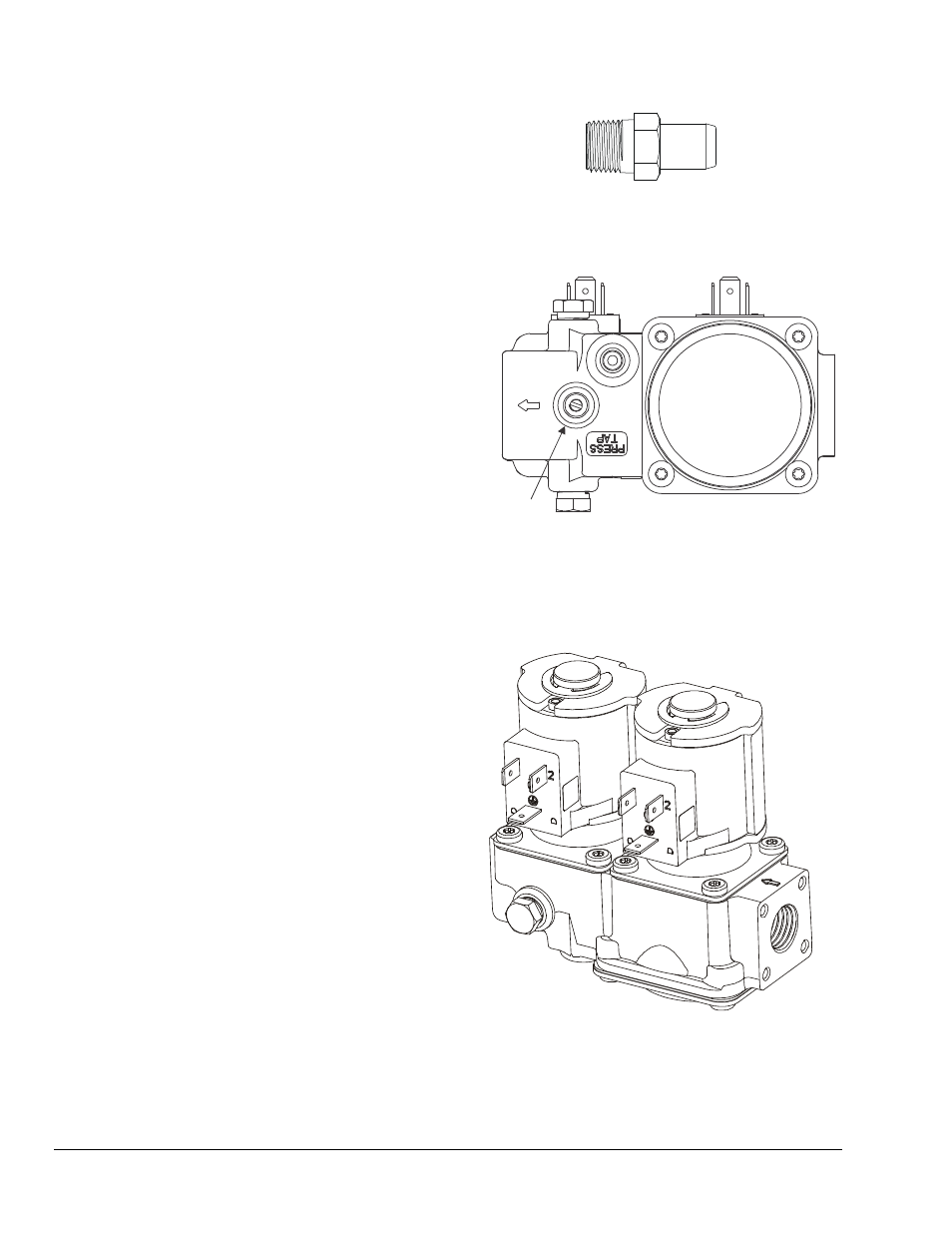
7. If you desire to measure the outlet pressure, use
the bottom cast pressure test fitting or use the
Y99AX pressure test fitting (see Figure 2) and an
approved pipe joint compound on the male
threads and screw the fitting into either side of the
valve, which ever side is convenient, replacing the
pressure tap plug.
8. Check for leakage.
a. Shut off the gas at the main manual shutoff
valve and open the pressure connection
between the manual shutoff valve and the
BGD258 valve.
b. Connect air tubing with a maximum pressure
of 1-1/2 times the valve’s maximum operating
pressure (as indicated on the valve) to the
opened pressure connection.
c. Paint all valve body connections and bleed
hole with a rich soap and water solution.
If bubbles occur, this is an indication of a leak.
To stop a leak, tighten joints and connections.
Replace the part if the leak cannot be stopped.
If bubbles do not occur, remove the air tubing
and close the pressure connection.
9. Make wiring connections. Refer to the Wiring
section for specific wiring instructions.
10. To measure the outlet pressure, turn the screw in
a counterclockwise direction one or two turns in
the fitting and fit a 9 mm diameter flexible tube
over the fitting. Proceed to operate the valve and
observe the outlet pressure.
11. Once the operation of the valve and the
observation of the outlet pressure is complete, turn
off power to both valve solenoids. Remove the
flexible tube and tighten the needle screw by
turning it clockwise with a slotted screwdriver until
hand tight, sealing the bleed hole.
Figure 2: Y99AX-1 (1/8-27 NPT) Pressure Test Fitting
Y99AX-2 (1/8-28 BSPT) Pressure Test
Fitting
Outlet Pressure
Tap Connection
Figure 3: Underside of Valve
12. Before leaving the installation, observe at least
three complete operating cycles to ensure that all
components are functioning correctly. Make sure
bleed hole is leak tight (review 8c for leakage test).
Figure 4: BGD258 Gas Valve