Avlink HX-2388 User Manual
Page 11
Matrix Switching System—User Manual
10
LAN Port: Use the RJ-45 connection cable to connect the Internet and the HDMI
matrix device. The entire PC at the same network can control the HDMI matrix device
through the LAN port.
IN1~8: Depend on the built-in modules, HDMI matrix device Input Channels are
connected to the DVDs or HDMI-LP, for more information please refers to Appendix A.
OUT1~8: Depend on the built-in modules, HDMI matrix device Output Channels are
connected to the HDTVs or HDMI-RP, for more information please refers to Appendix
A.
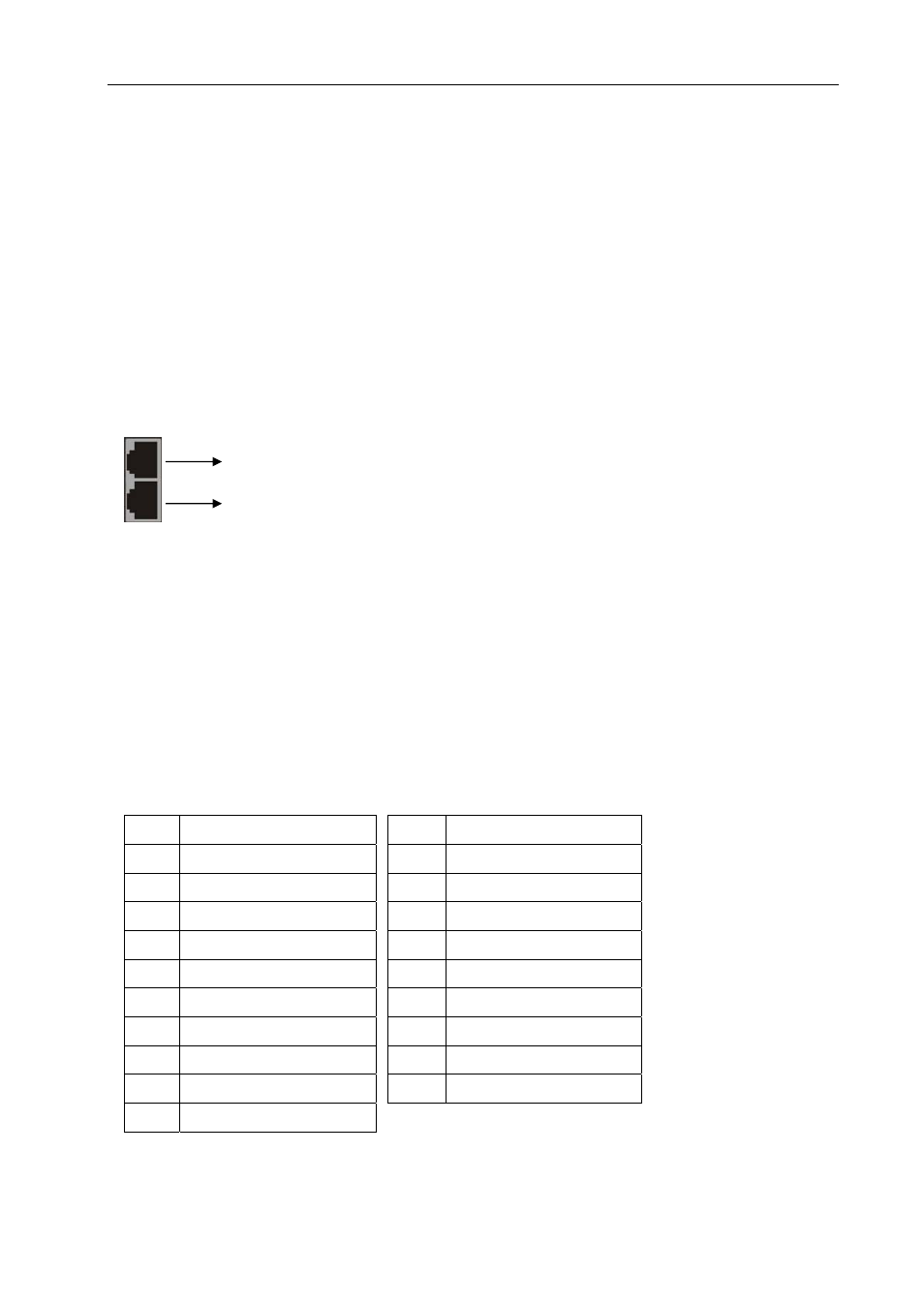
When using the extender port modules, up port is for DDC function, down port is for
VIDEO function.
) For RJ-45 Connector daughter board modules equipment, the connection has a
collocation with HDMI-EP; please refer to the Appendix A for more information.
Daughter board modules:
MX-HDI1 HDMI Connector input
MX-HDO1 HDMI Connector output
MX-RJI1 RJ-45 Connector input (for extender port)
MX-RJO1 RJ-45 Connector output (for extender port)
HDMI Type A Connector pin definition:
Pin #
Signal
Pin #
Signal
1
TMDS Data2+
11
TMDS Clock Shield
2
TMDS Data2 Shield
12
TMDS Clock-
3 TMDS
Data2-
13
NC
4 TMDS
Data1+
14
NC
5
TMDS Data1 Shield
15
DDC-SCL
6 TMDS
Data1-
16 DDC-SDA
7 TMDS
Data0+
17 DDC-Ground
8
TMDS Data0 Shield
18
+5V Power
9 TMDS
Data0-
19
Hot Plug Detect
10 TMDS
Clock+
DDC function
VIDEO function