Chapter 6 - safety device testing, Safety device testing, Chapter 6 safety device testing – AERCO BMK 3.0 LN Dual Fuel June 2010 User Manual
Page 49
SAFETY DEVICE TESTING
CHAPTER 6 SAFETY DEVICE TESTING
6.1 TESTING OF SAFETY DEVICES
Periodic safety device testing is required to
ensure that the control system and safety
devices are operating properly. The Benchmark
3.0 Dual-Fuel control system comprehensively
monitors all combustion-related safety devices
before, during and after the start sequence. The
following tests check to ensure that the system
is operating as designed.
Operating controls and safety devices should be
tested on a regular basis or following service or
replacement. All testing must conform to local
codes such as ASME CSD-1.
NOTE
MANUAL and AUTO modes of operation
are required to perform the following
tests. For a complete explanation of these
modes, see Chapter 3.
NOTE
It will be necessary to remove the front
door and side panels from the unit to
perform the following tests.
WARNING
ELECTRICAL VOLTAGES IN THIS
SYSTEM MAY INCLUDE 460, 220,
120 AND 24 VOLTS AC. POWER
MUST BE REMOVED PRIOR TO
PERFORMING WIRE REMOVAL OR
OTHER TEST PROCEDURES THAT
CAN RESULT IN ELECTRICAL
SHOCK.
6.2 NATURAL GAS LOW GAS
PRESSURE SWITCH TEST
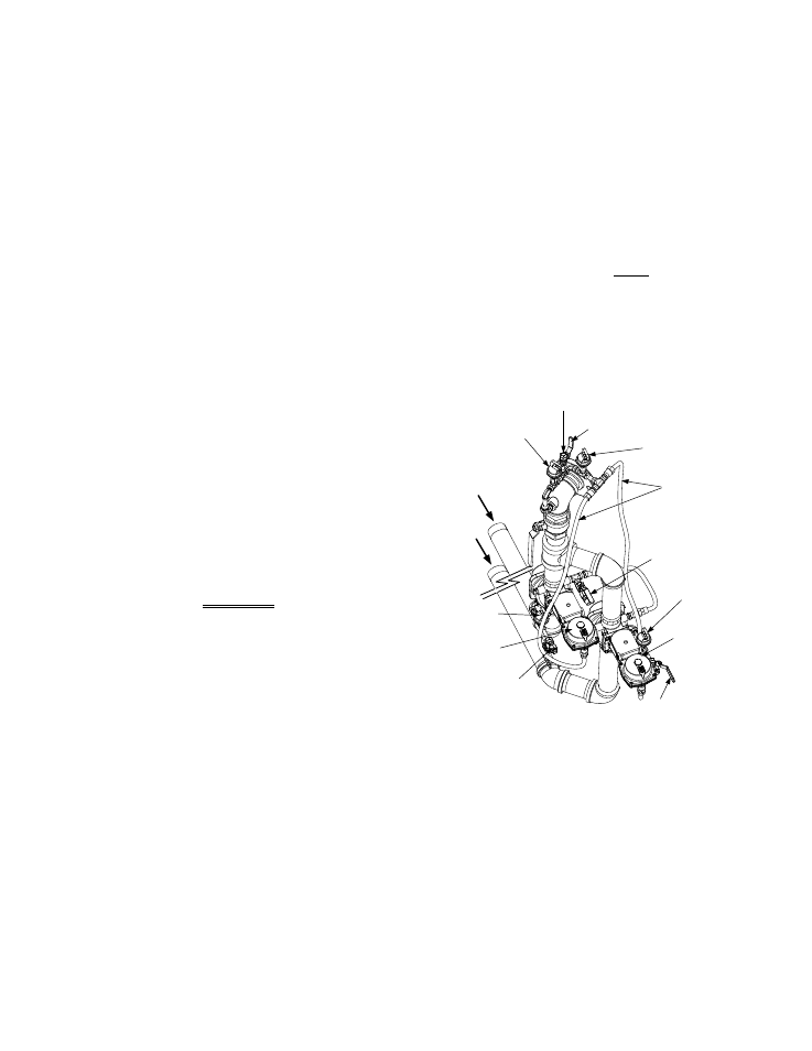
Refer to Figure 6-1 and ensure that the leak
detection ball valve located at the top of the gas
train by the high gas pressure switches is
closed.
1. Ensure that the Fuel Selector Switch (Figure
4-3) is set to the NATURAL GAS position.
2. Remove the 1/8 “ plug from the ball valve at
the natural gas low gas pressure switch
shown in the lower-left portion of Figure 6-1.
3. Install a 0 – 16 “ W.C. manometer or a W.C.
gauge where the 1/8" plug was removed.
4. Slowly open the ball valve near the low gas
pressure switch.
5. Place the unit in Manual Mode and adjust
the valve position between 25 and 30%.
6. While the unit is firing, slowly close the
external manual gas shut-off valve.
7. The unit should shut down and display a
LOW GAS PRESSURE
fault message at
approximately 2.6” W.C. The FAULT indi-
cator should also start flashing.
1/8" NPT PLUG
(INSTALL MANOMETER HERE FOR
HIGH GAS PRESSURE TEST)
LEAK DETECTION
BALL VALVE
PROPANE HIGH
GAS PRESSURE
SWITCH
NATURAL
GAS SSOV
PROPANE
SSOV
NATURAL GAS
LOW GAS
PRESSURE
SWITCH
BALL
VALVE
STAGED IGNITION
1/4" BALL VALVE
NAT. GAS &
PROPANE
PRESSURE
REGULATOR
FEEDBACK
LINES
NATURAL GAS
HIGH GAS
PRESSURE
SWITCH
PROPANE
INLET
NAT. GAS
INLET
PROPANE
LOW GAS
PRESSURE
SWITCH
1/8" NPT PLUG
(INSTALL MANOMETER
HERE FOR GAS
PRESSURE TEST)
Figure 6-1
Low & High Gas Pressure Testing
8. Fully open the external manual gas shut-off
valve and press the CLEAR button on the
Control Box.
9. The fault message should clear and the
FAULT
indicator should go off. The unit
should restart.
10. Upon test completion, close the ball valve
and remove the manometer. Replace the
1/8 “ plug removed in step 2.
6-1