Chapter 6 - safety device testing procedures, 1 testing of safety devices, 2 low gas pressure fault test – AERCO BMK 2.0 LN Nat. Gas User Manual
Page 43: 3 high gas pressure test, Safety device testing
SAFETY DEVICE TESTING
6-1
Chapter 6 - SAFETY DEVICE TESTING PROCEDURES
6.1 TESTING OF SAFETY DEVICES
Periodic safety device testing is required to
ensure that the control system and safety
devices are operating as designed. The AERCO
control system comprehensively monitors all
combustion related safety devices before, during
and after the start sequence. The following tests
have been chosen to ensure that the system will
either not start or will shut-down as intended.
Operating and safety controls should be tested
on a regular basis or after a safety device has
been serviced or replaced. All testing must
conform to local codes such as ASME CSD-1.
NOTE:
MANUAL and AUTO modes are required to
perform the following tests. For a complete
explanation of these modes, see Chapter 3.
NOTE:
It will be necessary to remove the sheet
metal covers from the unit to perform the
following tests.
WARNING!
ELECTRICAL VOLTAGES IN THIS
SYSTEM MAY INCLUDE 460, 220, 120
AND 24 VOLTS AC. POWER MUST BE
REMOVED PRIOR TO PERFORMING
WIRE REMOVAL OR OTHER TESTING
PROCEDURES THAT CAN RESULT IN
ELECTRICAL SHOCK.
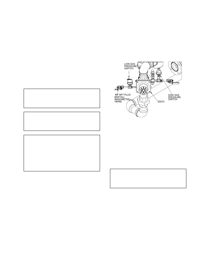
6.2 LOW GAS PRESSURE FAULT TEST
1. Referring to Figure 6.1, ensure that the 1/8"
NPT ball valve upstream of the SSOV is
closed (located at low gas pressure switch).
2. Remove the 1/8" plug from the ball valve,
upstream of the safety shutoff valve (SSOV).
3. Install a 0-16" W.C. manometer or W.C.
gauge where the 1/8" plug was removed.
4. Slowly open the 1/8" ball valve upstream of
the SSOV.
5. Place the unit in Manual Mode and fire the
unit at a firing rate between 25% and 30%.
6. While the unit is firing, slowly close the Man-
ual gas shut-off valve located immediately
outside the boiler. The unit should shut down
on a LOW GAS PRESSURE fault message
at 4.4” W.C. For Benchmark 2.0 Low NOx
boilers configured for De-Rated capacity
(see para. 2.4.1), the unit should shut down
on a LOW GAS PRESSURE fault message
at 3.6” W.C.
Figure 6.1
1/8” Pipe Plug Position for Manometer
Installation & Low Gas Pressure Testing
7. Fully open the manual gas shut-off valve and
press the CLEAR button on the Control Box.
8. The unit should restart.
9. Remove manometer and replace 1/8”NPT
plug.
NOTE:
After faulting the unit, the fault message will
be displayed and the fault indicator light will
flash until the CLEAR button is pressed.
6.3 HIGH GAS PRESSURE TEST
1. Start the unit in manual mode and fire
between 25% and 30%.
2. Remove either wire # 150 or wire #151 from
the high gas pressure switch. See Fig. 6.1.
3. The unit should shut down on a HIGH GAS
PRESSURE FAULT.
4. Reconnect the wire previously removed from
the high gas pressure switch and depress
the CLEAR button.
5. The unit should restart.