Installation – AERCO BMK 2.0 LN Nat. Gas User Manual
Page 16
INSTALLATION
2-6
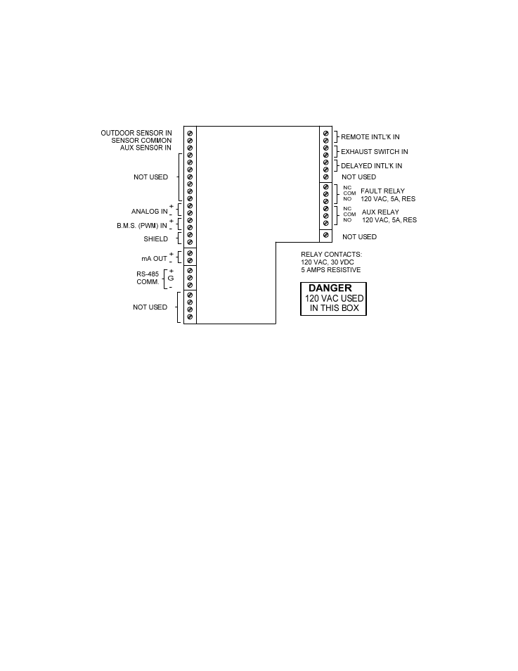
2.6.2 INDOOR/OUTDOOR RESET MODE
This mode of operation increases supply water
temperature as outdoor temperatures decrease.
An outside air temperature sensor (AERCO PN
122790) is required. The sensor MUST BE wired
to the I/O Box wiring terminals (see Fig. 2.9). For
more information concerning the outside air
sensor installation, refer to paragraph 2.7.1
Figure 2.9 I/O Box Terminal Strip
2.6.3 BOILER
MANAGEMENT
SYSTEM
(BMS) MODE
NOTE
BMS Model 168 can utilize either pulse
width modulation (PWM) or RS485
Modbus signaling to the Boiler. BMS II
Model 5R5-384 can utilize only RS485
signaling to the Boiler.
When using an AERCO Boiler Management
System (BMS), the field wiring is connected
between the BMS Panel and each Boiler’s I/O
Box terminal strip (Figure 2-9). Twisted shielded
pair wire from 18 to 22 AWG must be utilized for
the connections. The BMS Mode can utilize
either pulse width modulation (PWM) signaling,
or RS485 Modbus signaling. For PWM signaling,
connections are made from the AERCO Boiler
Management System to the B.M.S. (PWM) IN
terminals on the I/O Box terminal strip. For
RS485 Modbus signaling, connections are made
from the BMS to the RS485 COMM terminals on
the I/O Box terminal strip. Polarity must be
maintained and the shield must be connected
only at the AERCO BMS. The boiler end of the
shield must be left floating. For additional
instructions, refer to Chapter 5, paragraph 5.6 in
this manual. Also, refer to GF-108M (BMS
Model 168) and GF-124 (BMS II Model 5R5-
384), BMS -Operations Guides.
2.6.4 REMOTE SETPOINT and DIRECT
DRIVE MODES
The Benchmark Boiler can accept several types
of signal formats from an Energy Management
System or other source to control either the
setpoint (Remote Setpoint Mode) or firing rate
(Direct Drive Mode) of the Boiler. These formats
are:
4 to 20 mA/1 to 5 Vdc
0 to 20 mA/0 to 5 Vdc
PWM – (Pulse Width Modulated signal. See
paragraph 2.7.4)
Network – (RS485 Modbus. See para. 2.7.7)