Installing the controller, Installing the camera input unit, Connecting camera cables – KEYENCE XG-8700T User Manual
Page 5
5
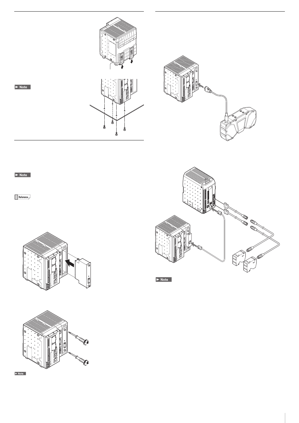
Installing the Controller
Installing the Controller on a DIN Rail
The controller unit and the expansion unit
are designed to be mounted on a DIN rail.
Pull out the tab on the bottom in the
direction of the arrow to mount or
dismount the controller.
Installing the Controller at the Bottom
Mount the controller in a stable location that is
free from vibration.
Installing the Camera Input Unit
Mount the optional camera input unit (XG-EC80T: for 3D cameras,
CA-EC80LJ/XG-EC80LJ: for the LJ-V, CA-EC80HX/CA-EC80L/
XG-EC80L: for HX Series cameras [when using 16x speed], or CA-EC80/
XG-EC80: for area scan cameras) to the camera slot of the controller.
Make sure that there is no power to the controller before connecting the camera
input unit. Connecting the camera input unit while connected to a power source may
damage the unit or controller.
The figure below explains the installation procedure for the optional camera input
unit XG-EC80T (for 3D cameras). Use the same procedure to install other camera
input units.
1
Remove the protective cover from the camera slot, and install
the camera input unit.
2
Tighten the upper and lower screws of the camera input unit to
fix the unit.
Tighten the screws to a torque of 1.5 [N·m].
Connecting Camera Cables
Connect the camera to the camera connector of the controller.
If connecting only a single camera, attach it to the camera 1 connector.
When connecting a 3D camera XR-HT*** with the camera input unit
XG-EC80T (for 3D cameras) attached
When connecting LJ-V with the camera input unit CA-EC80LJ/
XG-EC80LJ (for LJ-V) attached
• Bundle cables with a spiral tubing material. Direct bundling will concentrate the
cable load on the bindings, which can result in cable damage or short circuit.
• In the absence of other specifications, the minimum cable flexibility (R) should be 3
times the external diameter (5 times is recommended). Additionally, repeated
curvature and screw stress should be avoided. The minimum flexion is the same,
even when using flexible cable. Unless otherwise stated, use R100 or greater.
• Only CA-CH* camera cables can be used with high-speed cameras and 3D
cameras (XR-HT***).
• Use the Ethernet cable for LJ-V connection (OP-87736) or a commercial Ethernet
cable (category 7 or above, or 10GBASE-T-compatible one) when connecting LJ-V.
• If a different camera is connected, it may cause improper functioning, do not
connect to a different camera.
Tab
M4 screws
To Camera 1 connector
Camera 1
To Camera 1 connector
LJ-V Series Controller
(sold separately)
LJ-V Series Head
(sold separately)