Part names and functions – KEYENCE XG-8700T User Manual
Page 3
3
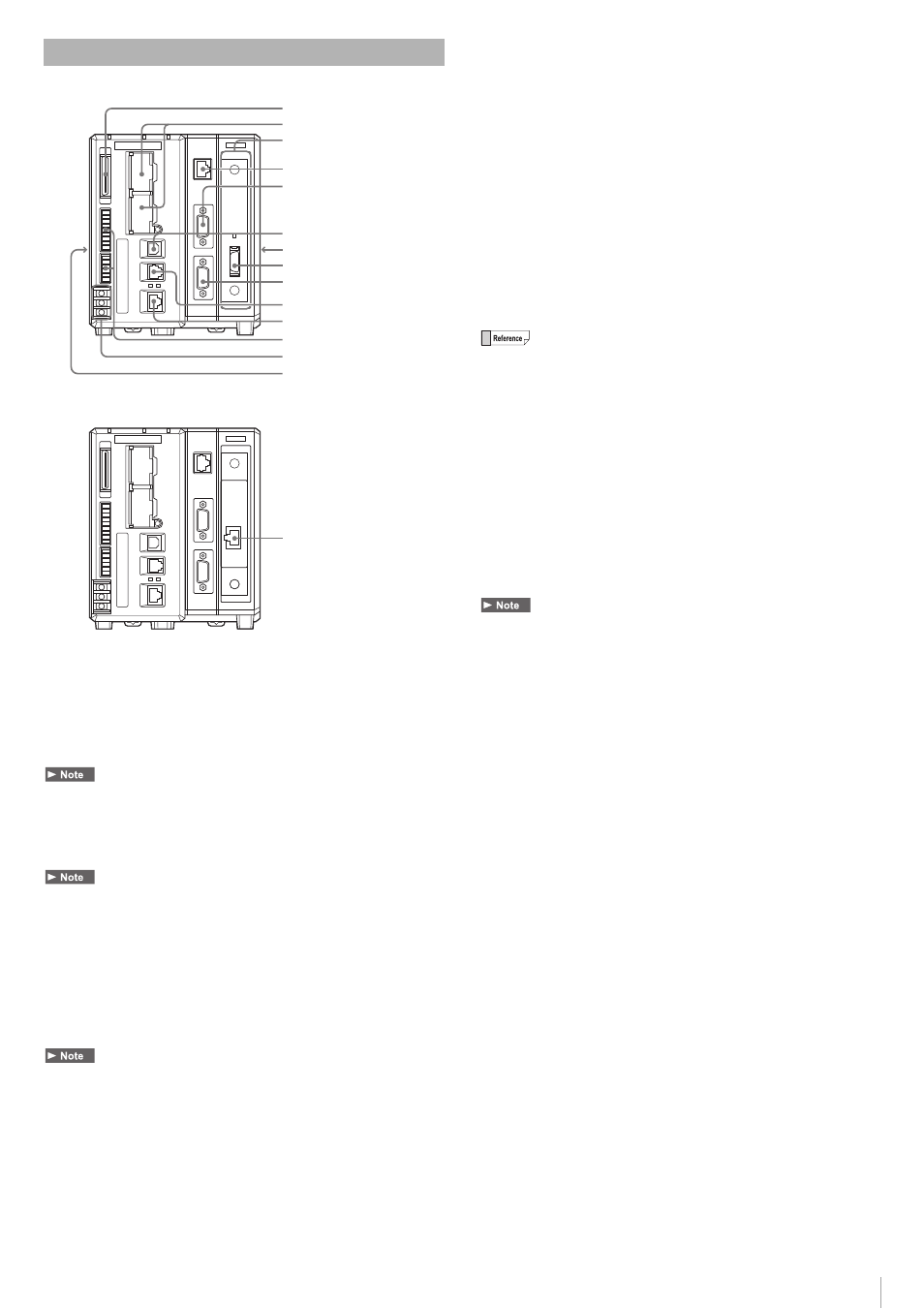
(1) Parallel I/O connector
Use to connect the parallel input/output signals.
(2) SD2 slot (upper), SD1 slot (lower)
Insert an SD card.
The lower slot (SD1) holds the included SD Card (CA-SD1G: 1GB) as SD
Card 1.
SD Card 1 must be inserted while the device is operating.
(3) Camera slot
Use to connect the camera input unit (At the time of shipping, the slot
holds nothing).
If the firmware of the camera input unit is old, an error message will be displayed at
the startup of the device. In this case, execute an update with the latest firmware
with the camera input unit attached.
(4) CONSOLE (Modular) connector
Use to connect to the console (OP-84231/OP-84236, sold separately) or to the
console connector cable (OP-87260: 3 m/OP-87261: 10 m, sold separately).
(5) MONITOR (RGB output) terminal
Use to connect to an Analog RGB Monitor.
• When using a commercially available Analog RGB Monitor other than the SVGA
(800 x 600 pixels), or XGA (1024 x 768 pixels), due to the specifications of the
Monitor, the image quality may become worse or the screen may not display
correctly (recommended monitor: CA-MP120T/MP120/MP81).
• When a program setting where XGA output is set is used in the main unit, always
connect a monitor that supports the XGA. When using a monitor that supports the
SVGA only, the screen may not display correctly.
(6) USB connector
Use to connect to the USB cable.
(7) Expansion unit connector 1 (right side)
Use to connect the camera expansion unit CA-E800/XG-E800.
(8) CAMERA 1 connector
Use to connect a 3D camera as camera 1.
(9) RS-232C Port 2
Connect the RS-232C Cable for the Touch Panel (OP-87258: 3 m/
OP-87259: 10 m, sold separately) or a commercially available RS-232C
Cable (D-sub9 Pin female).
(10) RS-232C Port 1
Connect the RS-232C Communication Cable (OP-26487: 2.5 m,
sold separately) or the RS-232C Modular Cable for the Touch Panel
(OP-87264: 3 m/ OP-87265: 10 m, sold separately).
For the default settings of the RS-232C Port: Port 1 is for data output and command
control, and Port 2 is for CA Series Touch Panel use. Concerning changes in the
settings refer to the XG-8000 Series User’s Manual.
(11) Ethernet connector
Use to connect the Ethernet cable.
(12) OUT1/IN1 Connector (Terminal Block 1)
Use the signal Input/Output (OUT1/IN1).
(13) Power Source/Grounding Terminal
Connect the power supply (24 VDC) and the grounding wire.
(14) Expansion unit connector 2 (left side)
Use to connect the illumination expansion unit CA-DC30E/DC21E or CC-Link
unit CA-NCL10E.
When connecting the lighting expansion unit CA-DC20E, the flash control is limited
to FLASH1-4.
(15) CAMERA 1 connector
Use to connect LJ-V as camera 1.
Part Names and Functions
(1)
(2)
(4)
(3)
(5)
(6)
(7)
(8)
(15)
(9)
(10)
(11)
(12)
(13)
(14)
With the
XG-EC80T
installed
With the CA-EC80LJ/
XG-EC80LJ
installed