Getting started, Package content and part names, Input/output terminals (sj-f2010/5010 only) – KEYENCE SJ-F5000 Series User Manual
Page 2: Installation and connection, Precautions for installation, Installing sj-f2000/5000 series, Connecting the sj-f2000/5000 series
2
Getting Started
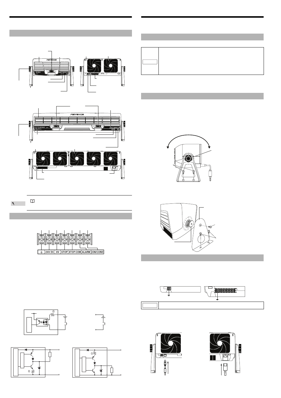
The package of SJ-F2000/5000 Series includes the following items. Ensure that these items are
included in your package before using the Unit. The name of each part is as follows.
• Static Elimination Blower Unit
SJ-F2000 series
SJ-F5000 series
• Instruction Manual x 1
• Grounding cable x 1
Layout of the input/output terminal block
[1] Ground terminal: Be sure to ground at a resistance not exceeding 100
Ω.
[2] 24 V DC terminal: DC24 ±10%
[3] 0V terminal: 0V for power and various alarm output
[4] Static elimination interruption input: To turn static elimination on/off, connect the DC24 V
voltage between [4] and [5].
[5] COM for static elimination interruption: COM terminal for static elimination interruption
[6] Alarm output terminal: Output when there is an alarm.
[7] Condition/Ion level alarm output terminal:
Output when the installation environment prevents static elimination from being properly executed or causes the
ion generation amount to decrease.
* The ground connection terminal [1] and the 0V terminal [3] are internally isolated.
Input/output circuit and the wiring method (SJ-F2010/5010 only)
z
Input circuit [static elimination interruption input]
z
Output circuit [Alarm, condition ion level alarm output]
Installation and Connection
This section explains how to set up and install the SJ-F2000/5000 Series.
Before installation, carefully verify the installation precautions for the SJ-F2000/5000 Series
and confirm the distance to the target object.
Installation location
Interference
SJ-F2000/5000 Series may not operate properly if multiple SJ-F2000/5000 Series are
installed close together, or if there are electrical conductors in the vicinity. Provide at least
50 mm of space when installing the unit.
There are two ways to install the SJ-F2000/5000 Series. The first is by using the stand
provided with this product, and the other is by using the L-type mounting bracket (SJ-F2000
series: OP-87147, SJ-F5000 series: OP-87148) or U-type mounting bracket (SJ-F2000 series:
OP-87149, SJ-F5000 series: OP-87150).
Installation method
z
Using the stand
Drill and tap (M4) the location where the SJ-F2000/5000 Series is to be installed, and
then use the M5 screw to secure the included stand.
z
Using L-type mounting bracket for the SJ-F2000/5000 series
(SJ-F2000 series: OP-87147, SJ-F5000 series: OP-87148)
Mount the SJ-F2000/5000 Series on the L-type mounting bracket for the SJ-F2000/5000
series. Drill and tap (M5) the location where the SJ-F2000/5000 Series is to be installed,
and then secure the bracket.
Connecting the grounding cable
Connect the provided grounding cable to the rear ground terminal, and then connect the
cable to the ground. For SJ-F2010/SJ-F5010, connect the provided grounding cable to the
ground connection terminal of the input/output terminal block.
Connecting to the power supply
To connect to the power supply, use one of the following methods.
Package content and part names
• A power supply is necessary to use SJ-F2000/5000 Series.
See "Installation and Connection" (page 2)
• The 0V and ground terminals for the 24 V DC IN connector of the SJ-F2000/
SJ-F2500 are non-insulated.
Input/output terminals (SJ-F2010/5010 only)
Condition/Ion level
Alarm indicator
Front cover
Lock switch
START/STOP button
Stand
Cursor key
Indicator
5 LEDs for SJ-F2000/SJ-F2010
7 LEDs for SJ-F2500
Rear cover
Air filter
Input/output terminal
block (SJ-F2010 only)
Ground terminal
(SJ-F2000/SJ-F2500 only)
24 V DC IN connector
(SJ-F2000/SJ-F2500 only)
Angle fixing
knob
Condition/Ion level
Alarm indicator
Front cover
Lock switch
START/STOP button
Stand
Cursor key
Indicator
5 LEDs for SJ-F5000/SJ-F5010
7 LEDs for SJ-F5500
Rear cover
Air filter
Input/output terminal block
(SJ-F5010 only)
Ground terminal
(SJ-F5000/SJ-F5500 only)
AC power inlet
(SJ-F5000/SJ-F5500 only)
Power switch
SJ-F5500 / SJ-F5000 only
Angle fixing
knob
Point
[1]
[2]
[3]
[4]
[5]
[6]
[7]
[4] Static elimination
interruption input
[4] Static elimination
interruption input
[5] COM for static elimination
interruption input
[5] COM for static elimination
interruption input
or
+24 V
+24 V
Main circuit
2 k
NPN open collector output
PNP open collector output
[2] 24 V DC
terminal
Main circuit
Overcurrent
protection circuit
24V DC
0V
[3] 0V terminal
*
* [6] Alarm
[7] Condition/ion level alarm
24V DC
0V
2.4
Main circuit
[3] 0V terminal
*
[2] 24 V DC
terminal
2.4
* [6] Alarm
[7] Condition/ion level alarm
Overcurrent
protection circuit
Load
Load
Precautions for installation
• Keep a space of at least 50 mm around the front and the rear of the
SJ-F2000/5000 Series.
• Keep a space of at least 20 mm around the bottom of the SJ-F5000 series.
• The installation location should withstand a load of at least 8 kg for the
SJ-F2000 series, and 20 kg for the SJ-F5000 series.
• Keep a tightening torque of no more than 1.5 N•m for the included stand,
the L-type mounting bracket, and the U-type mounting bracket (The
recommended tightening torque is 1.0 - 1.2 N•m).
Installing SJ-F2000/5000 Series
Connecting the SJ-F2000/5000 Series
For proper static elimination, be sure to ground the SJ-F2000/5000 Series at a
resistance not exceeding 100 Ω.
NOTICE
Loosen the angle fixing knob
to adjust the angle.
M4 screw
L-type mounting bracket
SJ-F2000 series: OP-87147
SJ-F5000 series: OP-87148
Buffer rubber
M5 screw
SJ-F2000 series: M5 screw
SJ-F5000 series: M8 screw
For SJ-F2000/SJ-F5000
SJ-F2500/SJ-F5500
For SJ-F2010/SJ-F5010
NOTICE
. For SJ-F2000/2500
Connect the AC adapter to the 24 VDC IN connector.
If a 24V power supply is being used, make sure
to use the 24VDC IN cable (OP-87152).
. For SJ-F5000/5500
Connect the AC cordset to the
AC power supply inlet.