Installation, Mounting instructions – Inovonics FA206DS User Manual
Page 2
© 1996 Inovonics Wireless Corporation
2
02154b.doc LIT-FA206DS-INSTALL hc:7-Aug-01
!"
Installation:
Mounting Note: Recommended mounting height range is 6'6" to 8'6". Recommended mounting
height is 7'6"(2.25m).
General mounting advice:
!" For best detection, locate the FA206DS so that intruders move across detection coverage patterns,
rather than toward or away from the sensor.
!" The mounting surface should be solid and vibration-free.
!" Check areas for potential sources of false alarms. Remember that the sensor responds to quick
changes in heat patterns within its coverage pattern. Avoid locating it where it is exposed to direct or
reflected sunlight, or to objects which can be heated quickly by sunlight. Do not place the FA206DS
looking at windows. Don't place it near heat or cold sources, like heater ducts or air conditioners, which
might direct hot or cold air onto the sensor. Look for appliances such as space heaters which can
rapidly heat up.
!" Find out about normal use of the area. Are there pets? Might there be birds, for example, in a
warehouse?
!" When the sensor might detect users who enter the protected area through a delayed door, program the
sensor as a "Follower" device.
!" Make end-users aware of the location of the FA206DS and caution them about obstructing the coverage
pattern when re-arranging furniture or stock.
Mounting Instructions:
The FA206DS may be mounted with or without the optional swivel or gimbal brackets. Without the brackets
the unit may be attached to walls or corners through the back of the detector housing.
Bracket Mount
Surface Mount
Surface Mount
Corner Mount
Corner Mount
Corner Mount
Corner Mount
Set screw
stop block
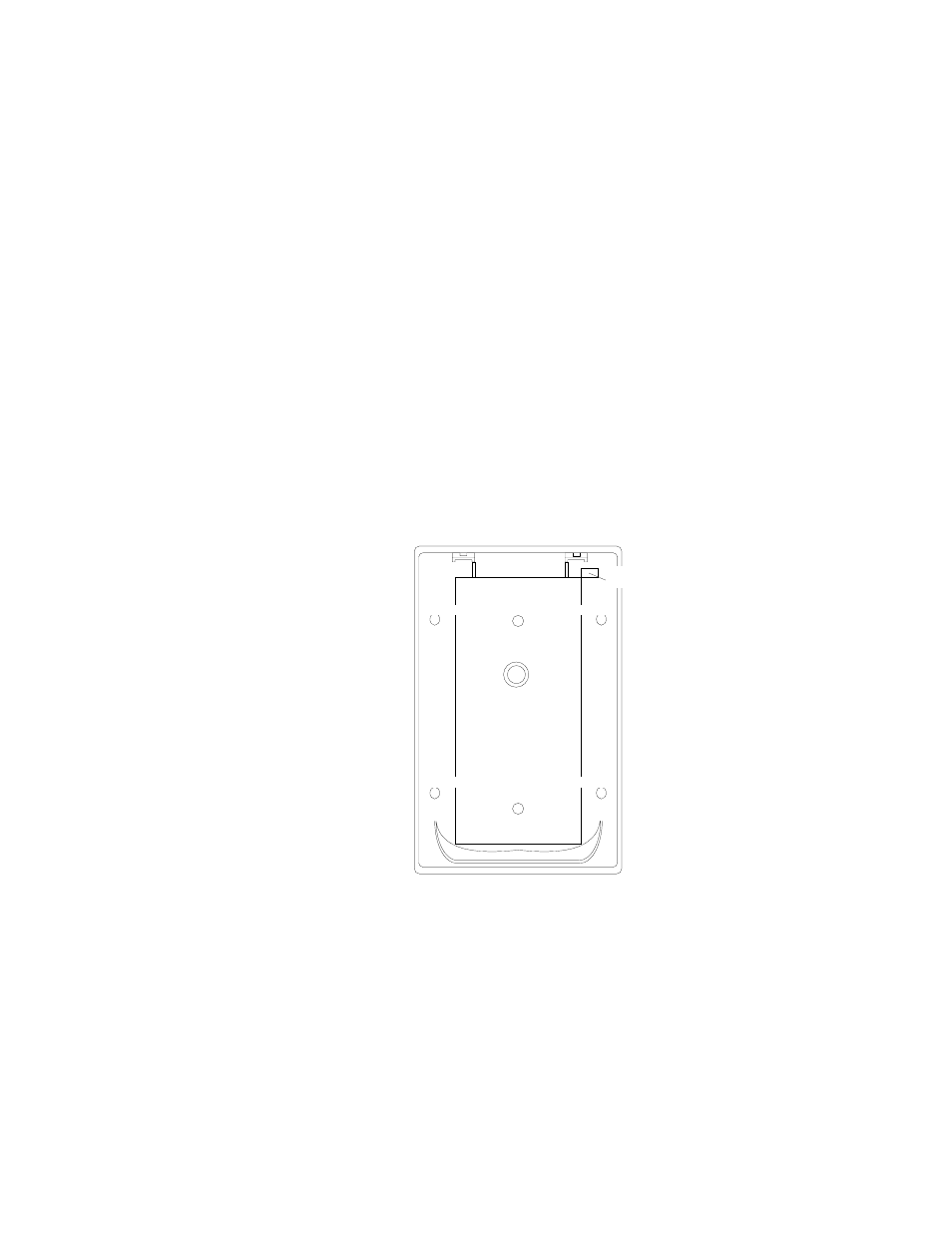
To mount the unit, first remove the cover by inserting a small screwdriver into the notch at the bottom of the
cover and prying up. Next, remove the circuit board/mirror unit from the enclosure. Unscrew the set screw
near the reset button enough to allow it to clear the stop block in the housing. Push the unit toward the top of
the enclosure until it clears the four retainer tabs. Then lift the board/mirror unit out of the enclosure.
For surface or corner mounting, open two holes in the rear housing. Mark the location for the mounting
screws, using the enclosure as a template. Pre-start the mounting screws.
Firmly mount the detector. Replace the circuit board/mirror assembly.