Important – Inovonics FA206B User Manual
Page 3
© 2003 Inovonics Wireless Corporation
3
03814a.doc LIT-FA206DS-INSTALL hc:24-Apr-03
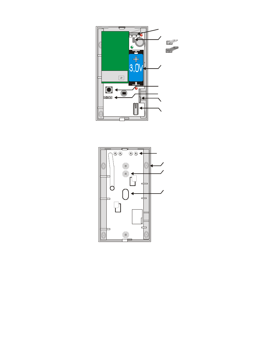
Next, remove the circuit board / mirror unit from the enclosure. Pull the PCB locking tab toward the side of
the housing, then lift the board / mirror unit out of the enclosure.
Wireless
Transmitter
PCB
Wall Tamper Switch
Wall Tamper Jumper
Reset Switch
Programming Jumper
Housing Tamper Switch
PCB Locking Tab
Battery
Jumper Off = Enabled
Jumper On = Disabled
For surface or corner mounting, drill two holes in the housing. Mark the location for the mounting screws,
using the enclosure as a template. Pre-start the mounting screws. Firmly mount the detector. Replace the
circuit board/mirror assembly.
Knockout for Wall Tamper (1 pl)
Corner Mount (4 pl)
Areas to remove if using
the B335 Bracket (3 pl)
Flat Surface Mount (3 pl)
Important!
Do not overtighten mounting screws!
Cover may not attach correctly.
- EE1215 (2 pages)
- EE1215W (2 pages)
- EE1216 (2 pages)
- EE1243 (3 pages)
- EE1247 (2 pages)
- EE1702 (1 page)
- EN1210 (2 pages)
- EN1210EOL (2 pages)
- EN1210W (2 pages)
- EN1212 (2 pages)
- EN1215EOL (2 pages)
- EN1215WEOL (2 pages)
- EN1216 (2 pages)
- EN1223D (2 pages)
- EN1223S (2 pages)
- EN1224 (2 pages)
- EN1233D (2 pages)
- EN1235SF (2 pages)
- EN1236D (2 pages)
- EN1238D (2 pages)
- EN1242 (3 pages)
- EN1247 (2 pages)
- EN1249 (2 pages)
- EN1252 (2 pages)
- EN1501 (2 pages)
- EN1501-EXT (4 pages)
- EN1702 (2 pages)
- EN1721 (2 pages)
- EN1722 (2 pages)
- FA100 (2 pages)
- FA113 (2 pages)
- FA200 (3 pages)
- FA200W (2 pages)
- FA201 (2 pages)
- FA203D (2 pages)
- FA204 (3 pages)
- FA205D (2 pages)
- FA206DS (8 pages)
- FA206S (8 pages)
- FA207 (2 pages)
- FA209 (3 pages)
- FA210 (2 pages)
- FA212 (2 pages)
- FA214 (2 pages)