Doepfer CTM64 Contact to Midi Interface (main board) User Manual
Page 15
CTM64 Version 4 - User's Guide
Page 15
Additional jumpers for pcb version 4
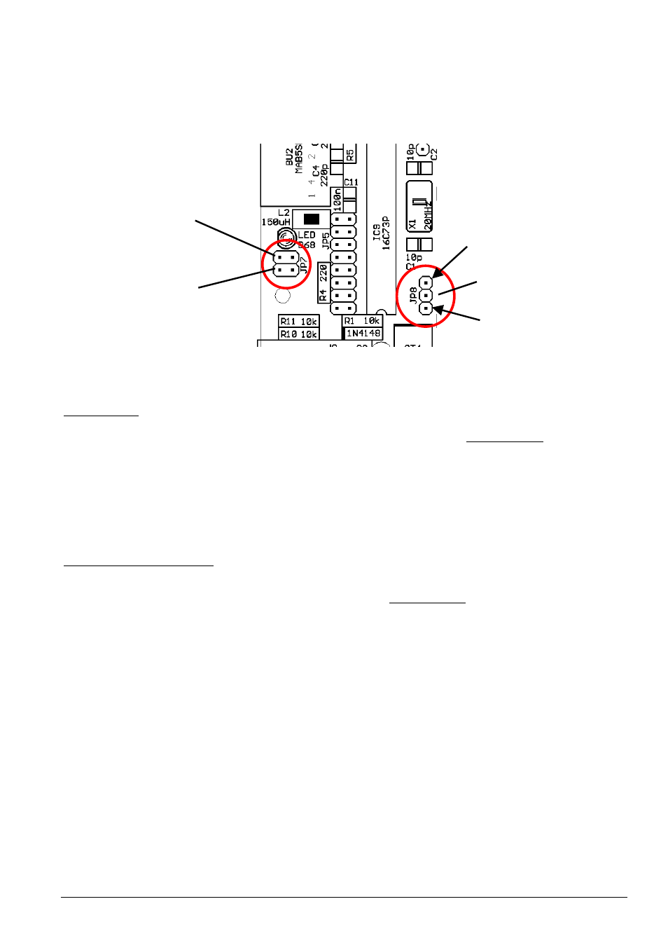
For version of the CTM64 e few more jumpers are available. The sketch below shows the position of
these additional jumpers.
The pin header JP7 is located near the LED between the MIDI out socket (BU2) and the foot switch
socket (BU4). The upper jumper of JP7 (next to the LED) is relevant only in the note mode:
64 note offset
• Jumper installed:
note offset as described above in this manual (factory setting)
• Jumper removed:
note offset = 64
The jumper has no meaning in the program change mode. This new feature was added to cover all 128
MIDI note values 0...127 with two daisy-chained CTM64 (e.g. for remote control of certain programs,
e.g. for Ableton Live).
The lower jumper of JP7 has this meaning:
Normal / Inverted operation
• Jumper installed:
normal mode, i.e. closing a contact generates a Midi note on message,
opening a contact generates a Midi note off messaged (factory setting)
• Jumper removed:
inverted mode, i.e. closing a contact generates a Midi note off message,
opening a contact generates a Midi note on (application example: "laser harp" with photo diodes or
light depending resistors)
Attention ! In this mode 64 note on messages are sent immediatly after power on if no (closed)
contacts are connected ! This may cause problems with Midi devices that have only small Midi input
buffers ! Even computers may have a problem with that and cause an Midi buffer overrun. Unused
inputs have to be connected to the common lead (JP6). Otherwise hanging notes will appear for
these terminals.
64 note offset
normal/inverted
operation
normal/toggle operation
GND
+5V