Operation – Doepfer CTM64 Contact to Midi Interface (main board) User Manual
Page 10
page 10
CTM64 Version 4 - User's Guide
Operation
CTM64 is switched ON by plugging the AC adapter into a wall outlet and connecting it to the
appropriate jack (1) on CTM64 pc board. There is no separate ON/OFF switch.
After power on the LED on the CTM64 will light up. Otherwise the AC adapter used is not suitable, has
the wrong polarity or does not work.
Now the CTM64 electronics is permanently checking out the following:
• if one of the 64 contacts is connected to the common pin (JP6) the corresponding MIDI message is
transmitted to MIDI Out (note or program change)
• if one of the potentiometers is turned the corresponding MIDI message is transmitted to MIDI Out
(pitch bend, modulation, volume or after touch)
• if the position of the sustain pedal connected to the jack socket is changed the corresponding MIDI
message is transmitted to MIDI Out
• if the setting of one of the jumpers (1-8) is changed the corresponding parameter (MIDI channel,
mode, offset/transpose) is changed
• if a MIDI message appears at MIDI In the message is transmitted to MIDI Out and merged with the
MIDI data of CTM64
It is possible to use switches or buttons instead of the jumpers 1-8. E.g. a hexadecimal coded rotary
switch can be used to select the MIDI channel, or toggle switches can be used as octave switch, offset
switch or mode switch.
If note mode is selected one has to pay attention that none of the 64 contacts is closed while MIDI
channel or offset/transpose is altered ! In this case the note off event (when opening the contact) would
be transmitted on another MIDI channel or note than the preceding note on event thus leading to
suspending notes !
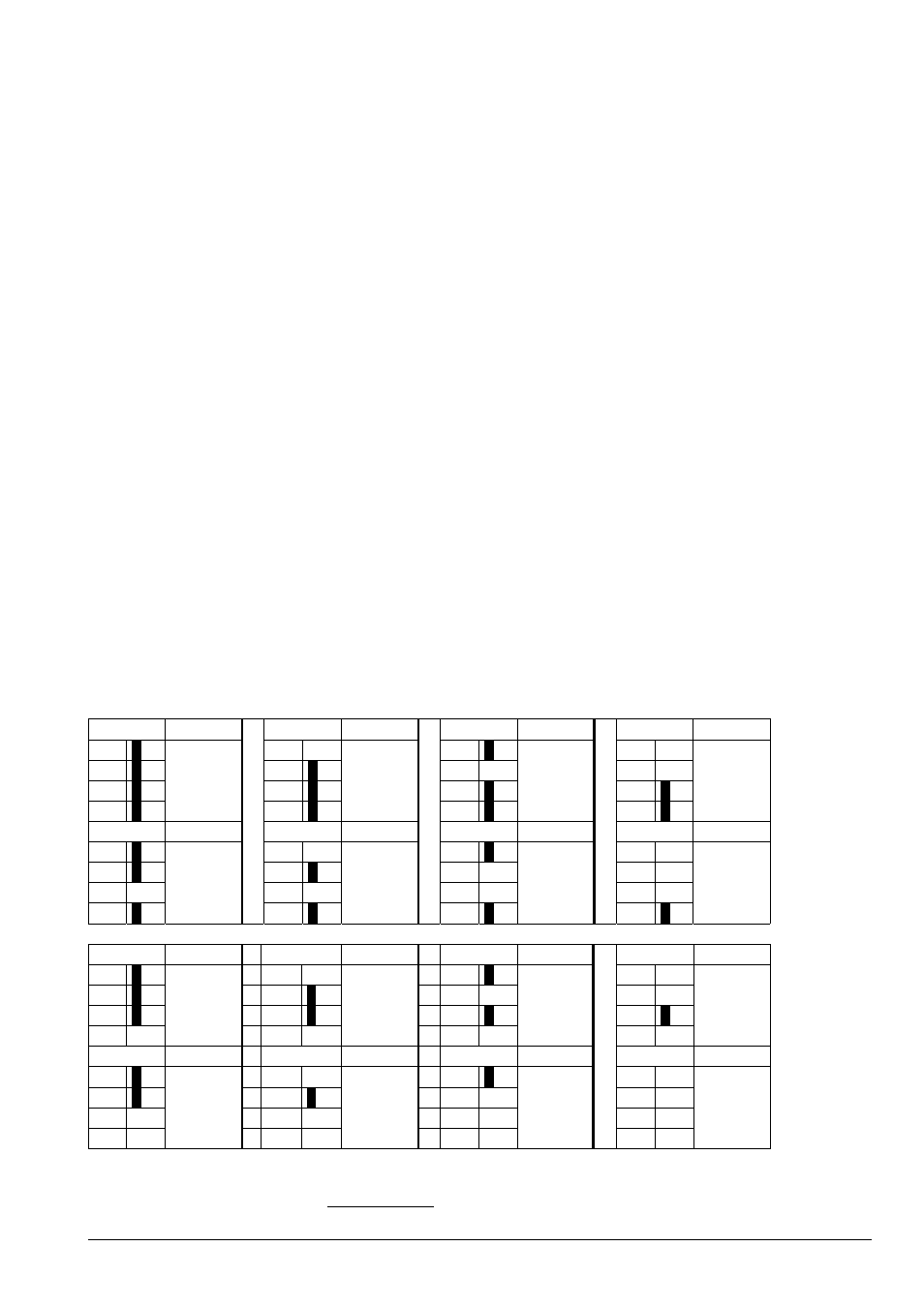
Detailed function of the 8 jumpers of JP5
Midi channel (jumper 1,2,3,4)
jumper
channel
jumper
channel
jumper
channel
jumper
channel
1
1
1
1
2
2
2
2
3
3
3
3
4
1
4
2
4
3
4
4
jumper
channel
jumper
channel
jumper
channel
jumper
channel
1
1
1
1
2
2
2
2
3
3
3
3
4
5
4
6
4
7
4
8
jumper
channel
jumper
channel
jumper
channel
jumper
channel
1
1
1
1
2
2
2
2
3
3
3
3
4
9
4
10
4
11
4
12
jumper
channel
jumper
channel
jumper
channel
jumper
channel
1
1
1
1
2
2
2
2
3
3
3
3
4
13
4
14
4
15
4
16
If a jumper is set the corresponding number is printed bold. E.g. for MIDI channel 1 all jumpers 1-4
have to be installed. This is the factory setting.