COP-USA ASH56NVIR-36S User Manual
Page 35
31
Fig.6
4.7.3 Wall-mounting
type
1) Take the wall-mounted supporting frame out of its packing, template with the chassis
of wall-mounted supporting frame to drill four holes for mounting M8 metallic
expansion bolts and respectively mounted with expansion pipe (shown as Fig.7);
Fig.7
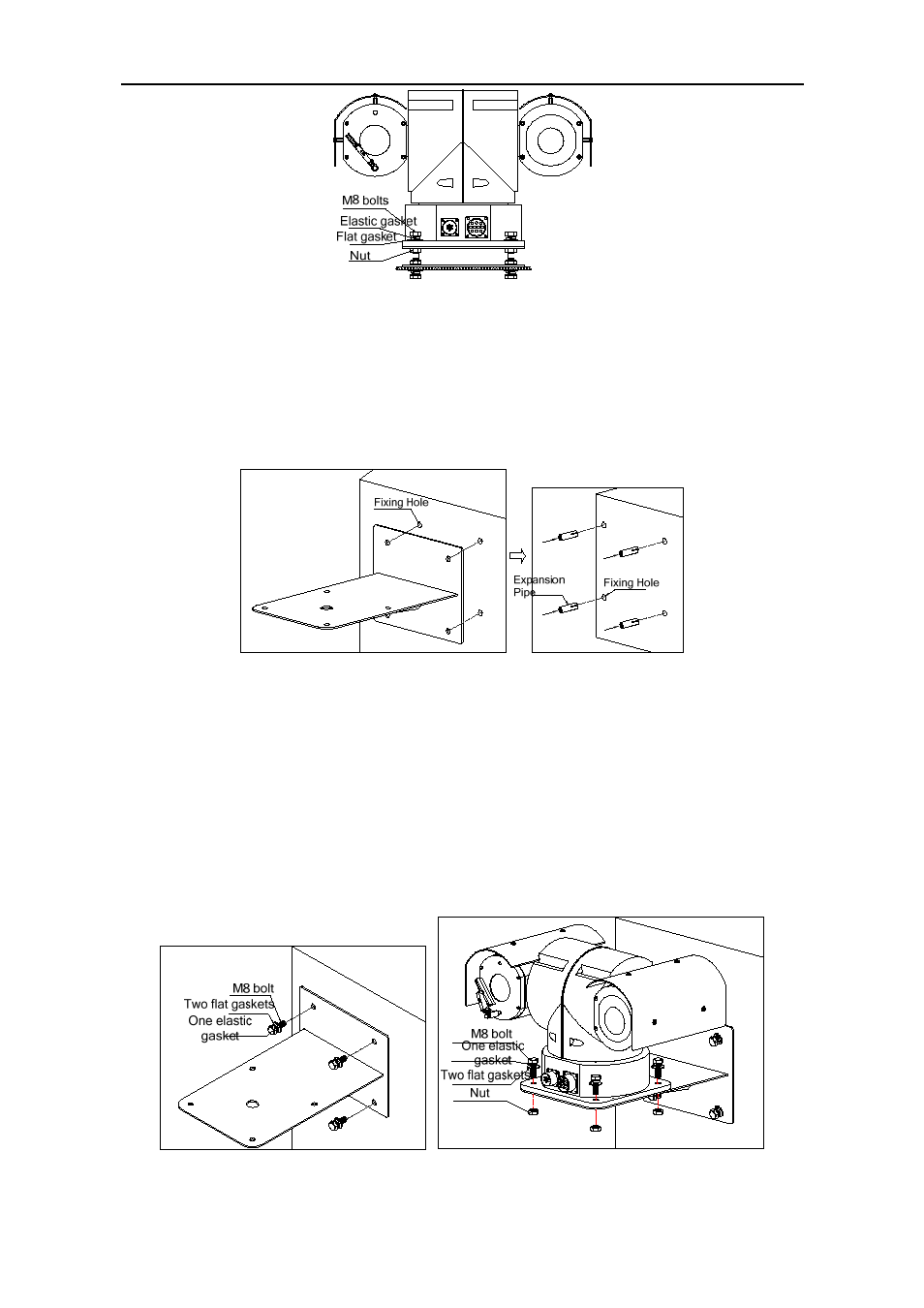
2) Take out the pan/tilt, pass the system control line, video line, and power cable
through the supporting frame, and fix it on wall with four M8 bolts and one φ8
elastic gasket and two φ8×φ18 SST flat gaskets (shown as Fig.8);
3) Then fix the pan/tilt securely on wall-mounting frame with four M8×30 SST bolts
and nuts with flat elastic gaskets (shown as Fig.9).
Fig.8 Fig.9