Chapter iii pan/tilt parameter setting – COP-USA ASH56NVIR-36S User Manual
Page 26
22
Chapter III pan/tilt parameter setting
Prior to install this product, please firstly confirm the communication protocol and baud
rate of system control host, then set the SW2DIP switch of pan/tilt according to that of
system, including SW1 setting of pan/tilt address, SW2 setting of communication protocol
type and baud rate.
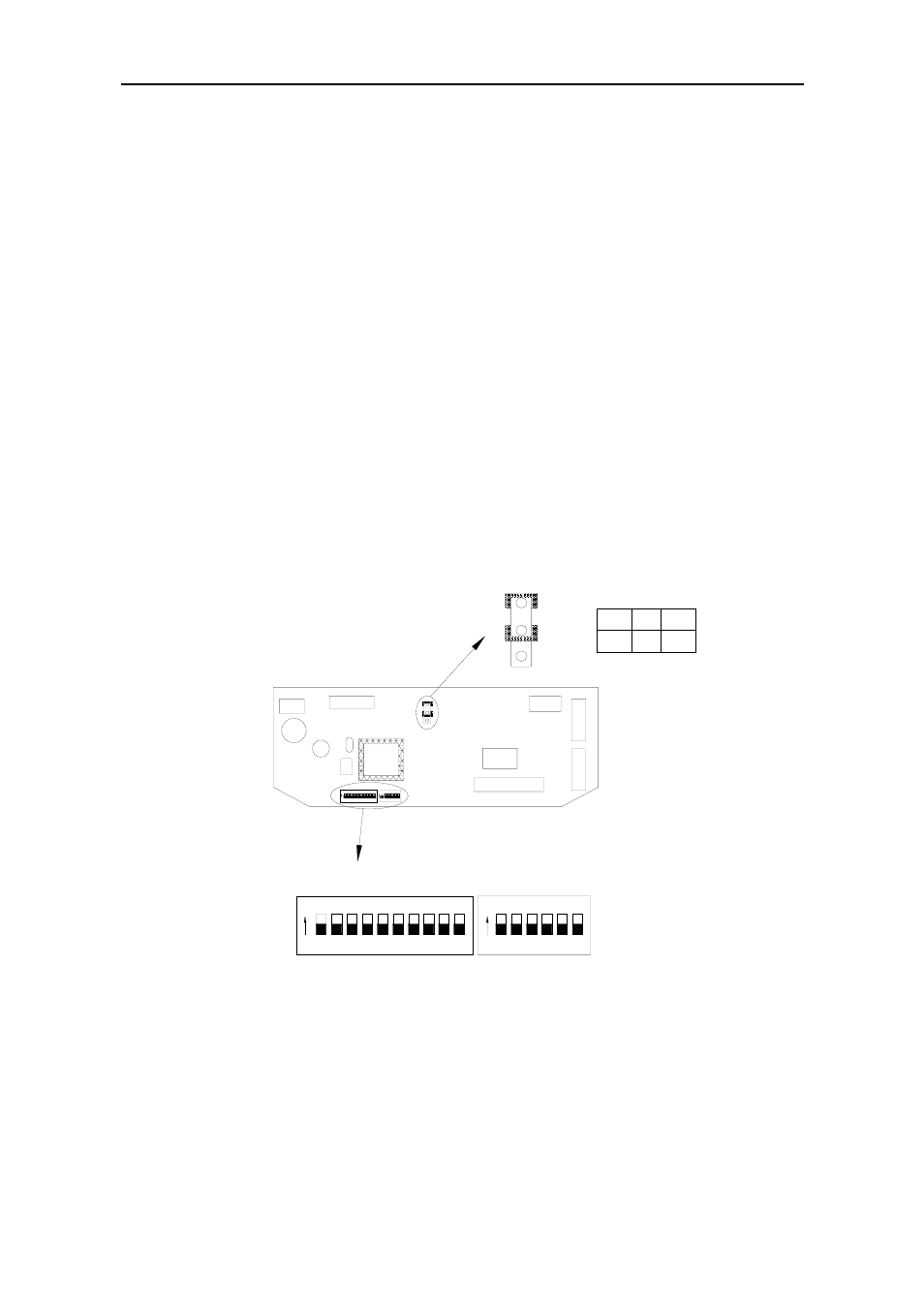
3.1 Setting of termination resistance
The JP1 jumper is the RS485 bus 120Ω termination resistance selecting switch. When it is
at 2—3 state,120Ω termination resistance is open, that is, no 485 bus terminated; when it
is under 1—2 state, 120Ω termination resistance is paralleled into 485 bus. In the whole
RS485 bus system, at most only one pan/tilt may connect the termination resistance into
circuit; all other pan/tilt shall let the termination resistance opening to increase the system
reliability. Usually the pan/tilt at the farthest end of control line may be connected, but the
termination resistances of all other equipment are opening.
4
1 2 3
5 6
10
7 8
6
5
3
2
OFF
2-3
ON
1-2
120R
JP1
3
2
1
2
3
JP
1
JP1
1
ON
1
4
9
ON
1 2 3 4 5 6
ON
7 8
9 10
4 5 6
1 2 3
ON
SW1 address setting DIP switch
Sw2 protocol selection
Fig.1
3.2 Setting of DIP address:
SW1 may set the pan/tilt address, with range 1~1023. From DIP-10 to DIP-1, it is
equivalent to a 10-bit binary number. DIP-10 is the highest bit; DIP-1 is the lowest bit.
The “ON” state of each bit indicates 1, and “OFF” indicates 0. The followings are the DIP
table of partial address code: