6 r s485 bus basic knowledge, Appendix – COP-USA CD58NV-MTS18 User Manual
Page 43
Characteristics of Rs485 Bus
Transmission distances of Rs485 Bus
Connection and termination resistor
As specified by Rs485 standard, Rs485 Bus is of
half-duplexed data transmission cables with chara-
cteristic impedance as 120 . The maximum load
capacity is 32 unit loads (including main controller
and controlled equipment.)
When user selects the 0.56mm(24AWG)twist-
ed pair wires as data transmission cable, the maxi-
mum theoretical transmitting distance are as foll-
ows:
If user selects thinner cables, or installs the do-
me in an environment with strong electromagnetic
interference, or connects lots of equipment to the
Rs485 Bus, the maximum transmitting distance w-
ill be decreased. To increase the maximum transm-
itting distance, do the contrary.
The Rs485 standard s require a daisy-chain Conn-
ection between the equipment. There must be ter-
mination resistors with 120
(as the picture 9-6.1).
Please refer to picture 9-6.2 for simple connection.
D should not exceed 7m.
9. 6 R s485 Bus Basic Knowledge
120
1#
2 #
3#
4#
32#
Picture9-6.1
120
120
1#
2#
3#
4#
32#
D
A+
B-
A+
B-
Picture9-6.2
120
2400BPS
4800BPS
9600BPS
1800m
1200m
80 0m
Baud rate
Max distan ce
19200BPS
60 0m
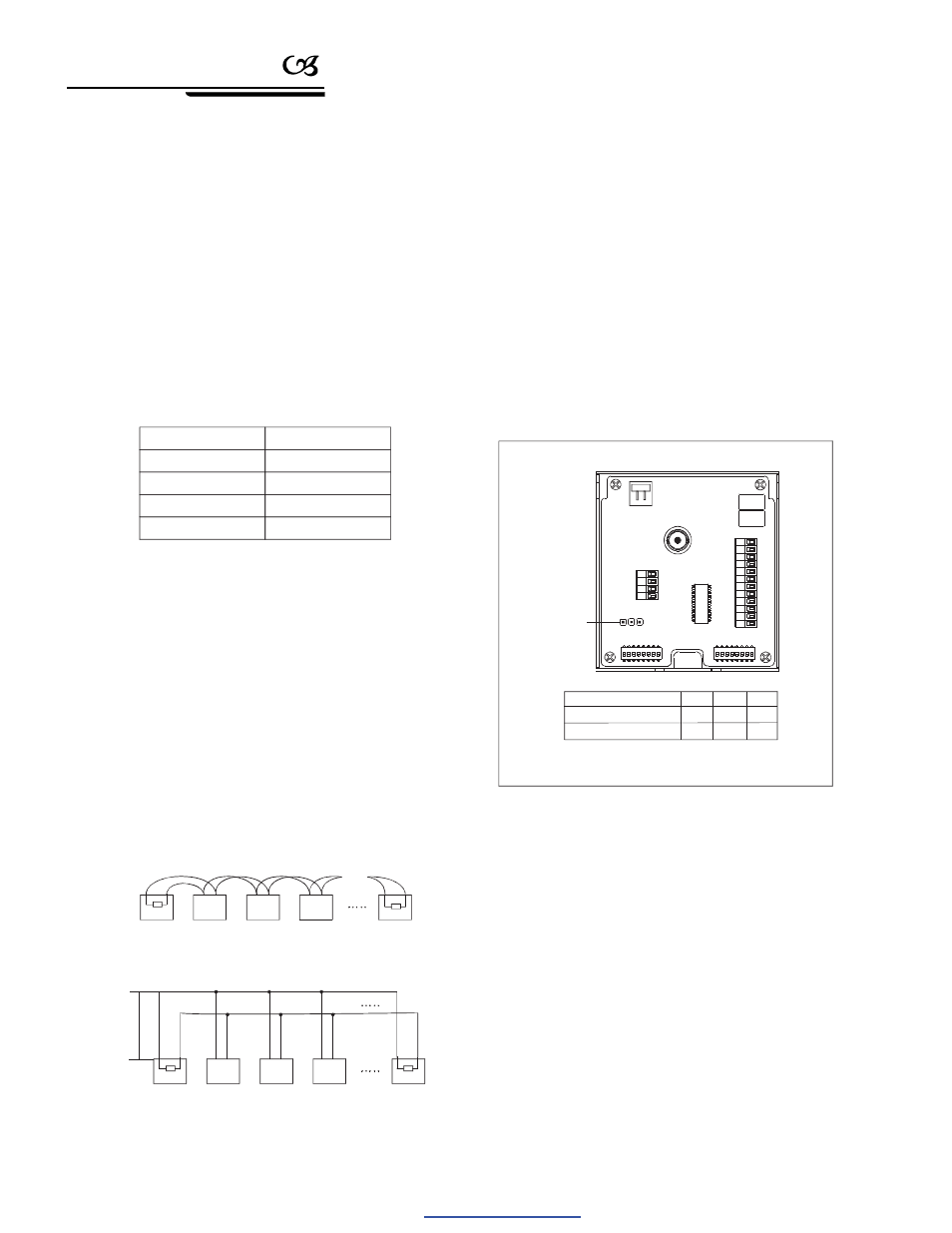
Set jumper line
position
1
2
3
Facto ry default setting
Connetction of 120 setting
1
2
3
ON
ON
OFF
On means insert the jumper cap.
OFF
ON
ON
Picture 9-6.3
The termination resistor is ready on the protocol PCB.
The are two kinds of connection(as show 9-6.3 form).
It is the factory default connection. The jumper cap of
switchboard is seated on p in 2 &pin 3 and the termin-
ation resistor120
is not connected.
When connecting the 120
termination resistor,
user should pull out the protocol PCB and plug the
jumper on pin1& pin2. Install the PCB back and the
termination resistor is con nected.(as show the p icture
9-6.3)
The connection of 120
termination resistor:
40
Appendix
PDF created with pdfFactory Pro trial version
www.pdffactory.com