Checkline TI-25M User Manual
Page 8
– 8 –
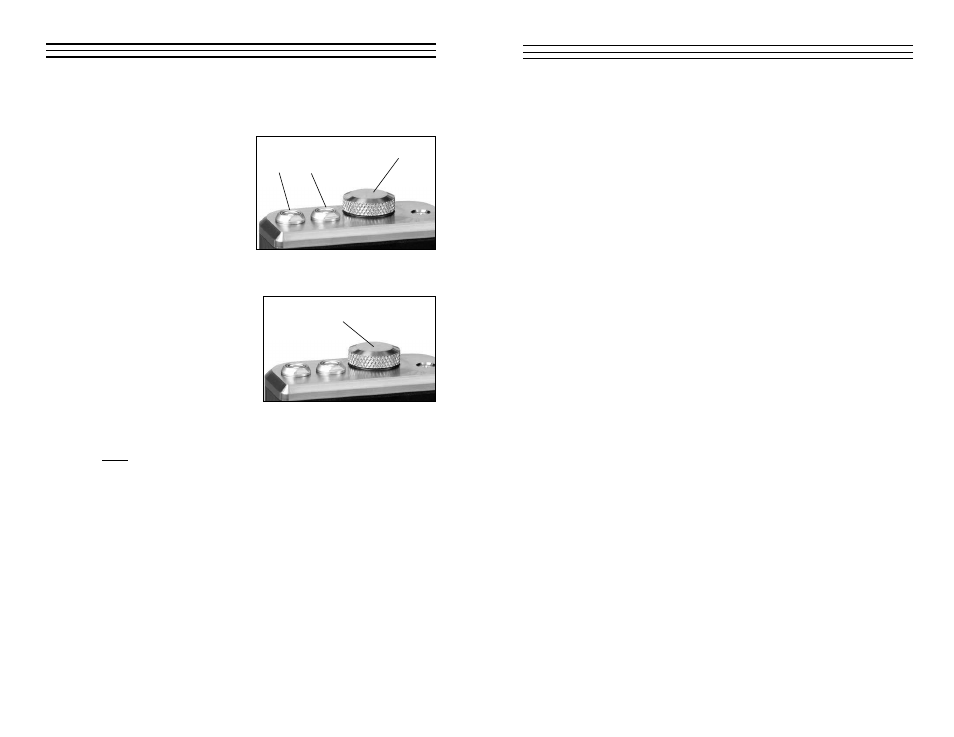
3.7 Probe Connector Receptacle
Located on the top edge of the TI-25M housing are the receptacles for the
probe and the probe zero plate.
The connectors for the probe
are non-polarized so the con-
nector at the end of the probe
cable can be inserted into
this receptacle in either
orientation. Make sure the
connector is “well seated” in
the receptacle.
3.8 Battery Compartment (Changing The Battery)
The battery compartment is
located under the probe zero
test plate. To open the battery
compartment, unscrew the
probe zero plate by rotating it
counterclockwise. The TI-25M
operates on two (2) AA
Batteries (1.5 V). If desired,
rechargeable batteries may be
used.
The TI-25M is shipped with the batteries installed. Insert batteries in the
polarity indicated on the rear label.
Note: When the display elements begin to flash off and on repeatedly, the
batteries are low and should be replaced.
Battery Cover
Probe Receptacles
Probe Zero
Plate
– 17 –
6.4 Changing Calibration — Two-Point Calibration Procedure
NOTE: This procedure requires two samples with "known" thickness
values are available during this calibration. The two samples should be at
the high and low portions of the expected range thickness that will be
encountered.
1. Turn on the gauge
2. Perform a Probe-Zero (refer to Section 4.3).
3. Apply couplant to the sample piece.
4. Press the transducer against the sample piece, at the first/second
calibration point, making sure that the transducer sits flat against
the surface of the sample. The display should show some (probably
incorrect) thickness value,and the Stability Indicator should have nearly
all its bars on.
5. Having achieved a stable reading, remove the transducer. If the
displayed thickness changes from the value shown while the transducer
was coupled,repeat step 4.
6. Press the CAL key. The IN (or MM) symbol should begin flashing.
7. Use the UP and DOWN arrow keys to adjust the displayed thickness up
or down, until it matches the thickness of the sample piece.
8. Press the PROBE-ZERO key. The display will flash 1OF2. Repeat
steps 3 through 7 on the second calibration point.
9. Press the PROBE-ZERO key again and the display will now show the
sound velocity value it has calculated based on the two known thickness
values that were entered.
10. The guage is now ready to perform measurements within this range on
that material.