Checkline TI-25M User Manual
Page 5
– 5 –
3.4 Keypad
The TI-25M is supplied with a membrane keypad mounted
on the front of the instrument body. It consists of six (6)
keys, each performing one or more functions as described
below.
The CAL key is used to enter and exit the Tl-25M’s two
Calibration modes. The Acoustic Velocity Calibration mode is
used to adjust the acoustic velocity for the material to be mea-
sured. The Measurement Calibration mode is used to increase or
decrease the displayed thickness reading to calibrate to a known
thickness value.
The INCH/MM key is used to change the measuring units from
inches to mm. Each time the key is pressed the units will change
from one to the other.
The UP arrow key performs the following two functions:
1. When in the Calibration mode, pressing the UP arrow
key will cause the numeric values to increase. By
pressing and holding the key, the numbers will change
more rapidly.
2. When in the Measuring mode, pressing the UP arrow key
will turn the Scan Measuring mode on and off each time
it is pressed. The display will momentarily flash indicating
whether the Scan mode is on or off.
The DOWN arrow key performs the following two functions:
1. When in the Calibration mode, pressing the DOWN
arrow key will cause the numeric values to decrease. By
pressing and holding the key, the numbers will change
more rapidly.
2. When in the Measuring mode, pressing the DOWN
arrow key will change the Display Backlight mode from
OFF to AUTO to ON. The currently selected mode will
momentarily flash on the display.
The PROBE ZERO key is used to “zero” the probe in a similar
way as a micrometer is “zeroed” before use. If the tool is not
zeroed correctly, the measurements will not be accurate.
The ON/OFF key is used to turn the power on as well as turning
the power off. If the Tl-25M is idle for five (5) minutes the gauge
will automatically power off.
CAL
INCH
MM
PROBE
ZERO
ON
OFF
CAL
PROBE
ZERO
INCH
MM
ON
OFF
– 20 –
6. If two materials are press-fitted or laminated together, the gauge
will only measure the thickness of the sample that contacts the
probe.
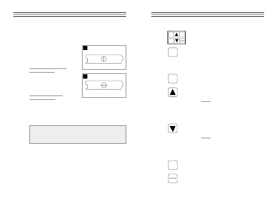
8.2 Measurements Of Pipes Or Cylindrical Parts
When using the TI-25M to
measure the wall thickness of
a pipe, the orientation of the
probe is very important to obtain
accurate readings.
Pipe diameter is greater than
4 inches (100 mm):
Position the probe so the centerline of
the probe wearface is perpendicular to
the long axis of the pipe as shown in
illustration “A.”
Pipe diameter is less than
4 inches (100 mm):
Two measurements should be performed at the same location, one with the
centerline of the probe perpendicular to the long axis and one parallel
(illustration “B”).
The smaller (thinner) of the two measurements should be used as the
actual wall thickness at the measurement location.
Additionally, on applications on pipe diameters less than 3 inches,
we recommend using the optional V-Block fixture which helps
maintain stable probe placement on the rounded measuring surface.
A
B
Parallel
Perpendicular