Checkline TI-25M User Manual
Page 6
– 6 –
3.5 LCD Display
The LCD Display provides the operator with important information as
detailed below. The display has a user-selected Backlight mode which can
be set for the following operation:
1. ON. The backlight is illuminated whenever the power is on.
2. OFF. The backlight is never illuminated (to save battery power).
3. AUTO. The backlight is automatically illuminated each time a
measurement is made.
The Backlight mode is set by pressing the key. Each time the key is
pressed, the mode will change from one to the other. “ON,” “OFF” or
“AUTO” will momentarily flash on the display indicating the currently set
Backlight mode..
• Measurement values
• Acoustic velocity values
• Units of measure
• Bar graph signal stability indicator
• Configuration messages
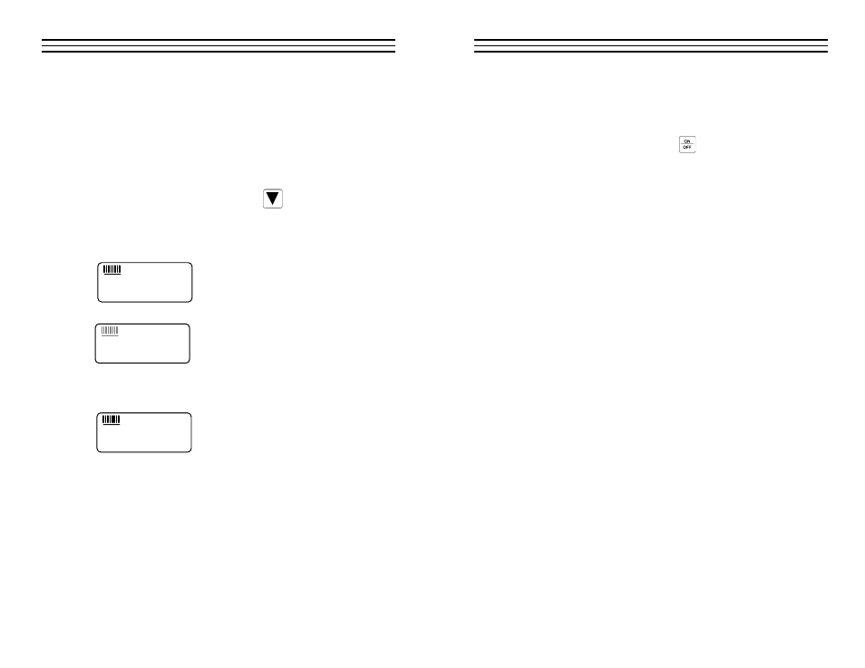
The numeric portion of the display consists of
4-digits preceded by a leading "1", and is used to
display numeric values, as well as occasional
simple words, to indicate the status of various
settings. When the TI-25M is displaying thick-
ness measurements, the display will retain the last measured value, until a
new measurement is performed.
The eight vertical bars shown form the Stability
Indicator. When the TI-25M is idle, only the
left-most bar and underline will be illuminated.
When a measurement is being performed, six or
seven bars should be illuminated indicating that it is a stable measurement.
If fewer than five bars are illuminated, the TI-25M is having difficulty
obtaining a stable and reliable measurement and the thickness value shown
should be ignored, as it is most likely erroneous.
1.8.8.8.8
+
IN MM/
µ
s
1.8.8.8.8
+
IN MM/
µ
s
1.8.8.8.8
+
IN MM/
µ
s
– 19 –
8 .0
M EASU RI N G PROCEDU RE
After setting the TI-25M for the correct acoustic velocity, or retaining the
factory-set acoustic velocity for steel, the gauge is ready to take wall thickness
measurements.
1. Turn on the power by pressing the key.
2. Plug the probe cable into the receptacle at the top of the gauge.
3. Place a small amount of coupling fluid on the surface to be
measured.
4. Grasp the probe by the molded rubber grip and place it on top
of the material surface. Apply moderate pressure to the top
surface of the probe with your index finger or thumb to
stabilize the probe and to keep the wearface seated flat against
the measurement surface.
5. The gauge will display the thickness of the steel wall along with the
Stability Indicator showing the relative stability of the reading.
6. Repeat steps #3 - #5 as required.
8.1 General Notes On Measurements
1. When the probe is removed from the sample after a
measurement, the last reading will be retained on the display.
2. If fewer than five (5) bars of the Stability Indicator are illuminated,
the thickness reading displayed is most likely inaccurate.
3. Occasionally, a small film of couplant will be drawn out between
the probe and the surface as the probe is removed. When this
happens, the TI-25M may perform a measurement that is larger or
smaller than it should be. This phenomenon is obvious when one
thickness value is observed while the probe is in contact with the
material, and another value after the probe is removed.
4. The gauge will automatically power off after 5 minutes of non-use.
5. The following surface conditions can prevent accurate
measurements (refer to section 4.6 Preparation Of The Surface):
• More than 0.020" (20 mils or 500 µm) of paint or other coating
• Flaking or loosely adhered coatings
• Rough or heavily pitted surface