3 setup – Checkline R55 User Manual
Page 5
Plug & Test
TM
Smart Force & Torque Sensors
User’s Guide
4
3 SETUP
The Plug & Test
TM
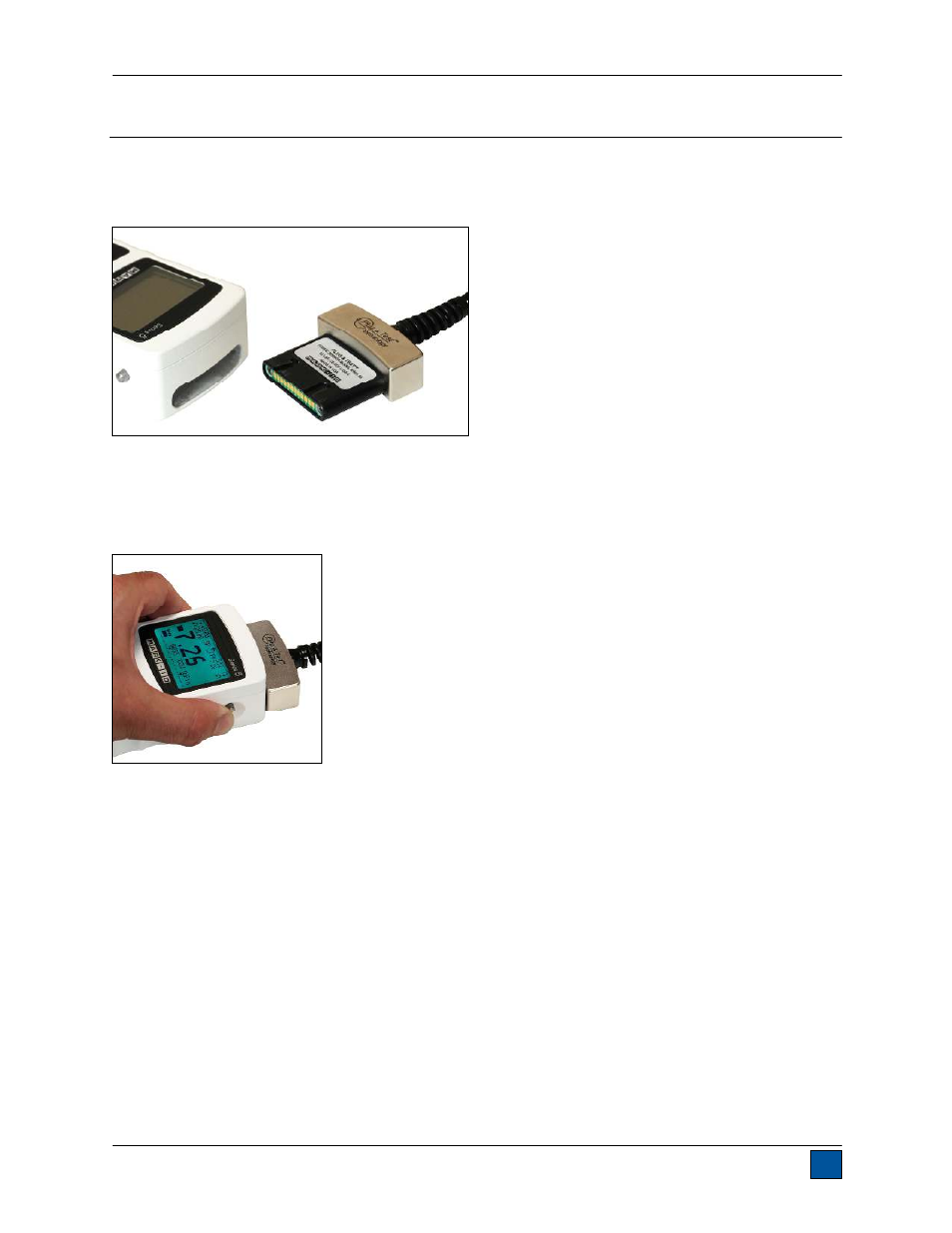
connector must be inserted into the receptacle of the indicator with the side marked
“Plug & Test
TM
Technology” facing up (see Fig. 3.1). When fully inserted, the connector will lock into place
with a “click”.
Fig. 3.1
Appropriate orientation of Plug & Test
TM
connector.
To release the connector, press both buttons on either side of the indicator housing to release the sensor
(see Fig. 3.2). Pull the connector completely out of the indicator by holding the curved aluminum section.
DO NOT pull on the cable or strain relief.
Fig. 3.2
Press both buttons on either side of the indicator housing to release the Plug & Test
TM
connector.
See also other documents in the category Checkline Measuring instruments:
- CDT-1000HD (6 pages)
- CDT-2000HD (9 pages)
- DT-105A (7 pages)
- DT-205LR (7 pages)
- PLT-5000 (7 pages)
- HTM (10 pages)
- YSL-2000HD (9 pages)
- DLM-107A (2 pages)
- A2105 (4 pages)
- DT-5TG (8 pages)
- MT2013 (2 pages)
- DT-209X (68 pages)
- WT3-200 (29 pages)
- WTT-110 (11 pages)
- WTT-110 (2 pages)
- WTTM-GEN1 (11 pages)
- TT-QC (10 pages)
- TT-QCM (16 pages)
- MTM (14 pages)
- ILTT (9 pages)
- TT02 (28 pages)
- TT Series (6 pages)
- DI-1M (6 pages)
- DIS-IP (6 pages)
- TT05 (26 pages)
- CAP-TNP (10 pages)
- TSTM (9 pages)
- ETW (11 pages)
- HTG2 (8 pages)
- AD-100 (10 pages)
- DD-100 (3 pages)
- HP Series (6 pages)
- HPSA-R (5 pages)
- EMS4 (27 pages)
- MKM (5 pages)
- MST (24 pages)
- MLT (18 pages)
- DT-5TS (20 pages)
- DIW (6 pages)
- DID-4 (6 pages)
- DIS-RL (6 pages)
- DSD-4 (4 pages)
- MGT (2 pages)
- CAP-TT01 (28 pages)