Checkline R55 User Manual
Page 11
Plug & Test
TM
Smart Force & Torque Sensors
User’s Guide
10
9 SERIES R50 TORQUE SENSORS
9.1 Unpacking and Assembly
Carefully remove the sensor from the box. For models MR50-10Z, MR50-
20Z, and MR50-50Z, remove the protective tubing inserted around the
chuck. Save it for future transportation needs. No assembly is required.
9.2 Overview
Designed for clockwise and counter-clockwise torque testing. The sensor
may be handheld or mounted to a test stand, fixture, or other equipment.
Bits or fixtures may be placed in the chuck, although extra care should be taken when handling low
capacity models.
9.3 Specifications
Accuracy:
±0.35% of full scale
Safe overload:
MR50-10Z - MR50-50Z: 300% of full scale
MR50-12 - MR50-100: 150% of full scale
Chuck opening range: MR50-10Z - MR50-50Z: 0.062 - 0.375 in [1.6 - 9.5 mm]
MR50-12 - MR50-100: 0.078 - 0.5 in [2.0 - 12.7 mm]
Operating temperature: 40ºF – 100ºF [5ºC – 38ºC]
Operating humidity:
96% max. (non-condensating)
Weight:
From 1.4 lb [0.6 kg]
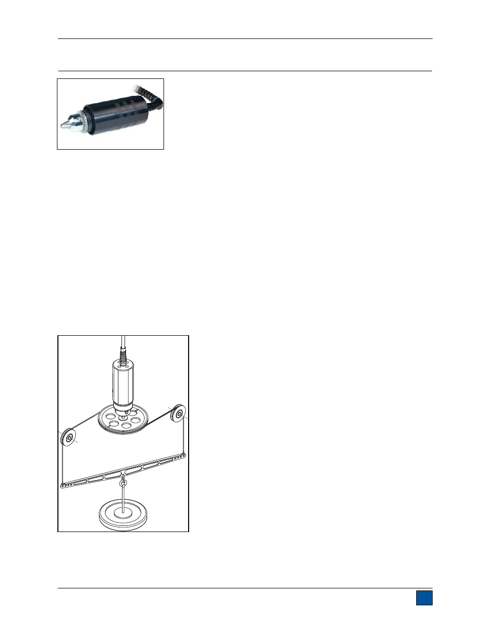
9.4 Calibration
Calibration should be performed in a vertical orientation, especially for sensors with capacities of 50 ozFin
[35 Ncm] or less. Horizontal orientation subjects the sensor to side loads resulting from the weight of the
chuck and attachments. Such side loads can be significant enough to skew the readings out of tolerance.
The illustration below depicts a recommended vertical setup:
For further calibration instructions, refer to the indicator’s user’s guide.