Checkline R55 User Manual
Page 13
Plug & Test
TM
Smart Force & Torque Sensors
User’s Guide
12
10 SERIES R51 TORQUE SENSORS
10.1 Unpacking and Assembly
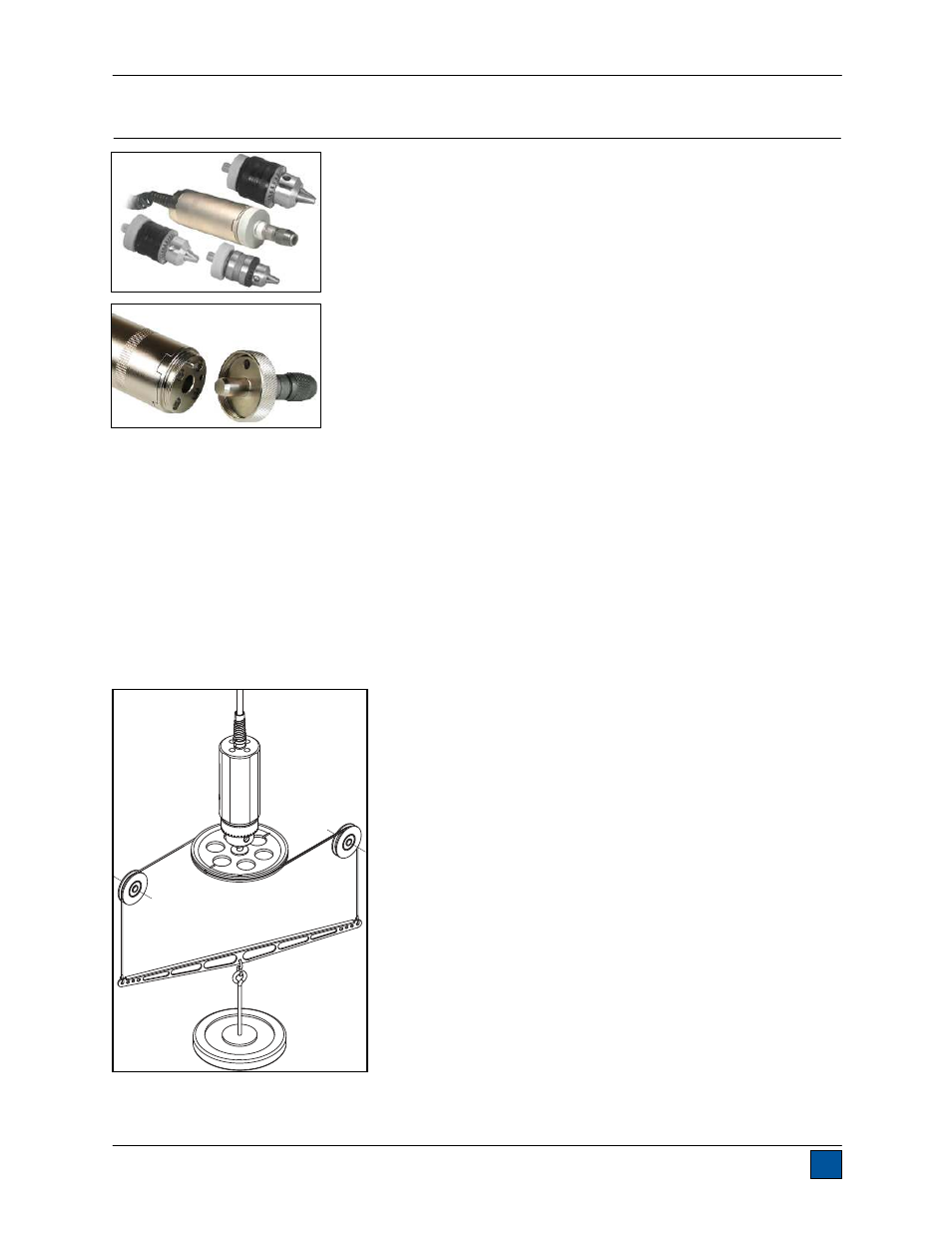
Carefully remove the sensor from the box. Series R51 sensors are
available with three interchangeable chuck attachments and bit holder.
To attach the chuck or bit holder, align the pin located on the end of the
sensor body with the hole located on the attachment (see Fig. 10.1).
Thread the ring onto the sensor body to keep the attachment in place.
10.2 Overview
Designed for clockwise and counter-clockwise torque testing. The sensor
may be handheld or mounted to a test stand, fixture, or other equipment.
Bits or fixtures may be placed in the chuck, although extra care should be
taken when handling low capacity models.
10.3 Specifications
Accuracy:
±0.2% of full scale
Safe overload:
MR50-10Z - MR50-50Z: 300% of full scale
MR50-12 - MR50-100: 150% of full scale
Chuck opening range: MR50-10Z - MR50-50Z: 0.062 - 0.375 in [1.6 - 9.5 mm]
MR50-12 - MR50-100: 0.078 - 0.5 in [2.0 - 12.7 mm]
Operating temperature: 40ºF – 100ºF [5ºC – 38ºC]
Operating humidity:
96% max. (non-condensating)
Weight:
From 1.4 lb [0.6 kg]
10.4 Calibration
Calibration should be performed in a vertical orientation, especially for sensors with capacities of 50 ozFin
[35 Ncm] or less. Horizontal orientation subjects the sensor to side loads resulting from the weight of the
chuck and attachments. Such side loads can be significant enough to skew the readings out of tolerance.
The illustration below depicts a recommended vertical setup:
For further calibration instructions, refer to the indicator’s user’s guide.
Fig. 10.1
The attachment and main sensor
body mate with a pin and threaded
ring.