Adjustment, 1 display panel, Figure 1 – Checkline FGS-100PV User Manual
Page 6
6
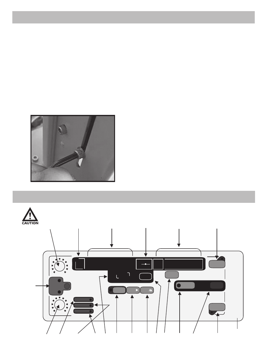
Adjustment
You can easily adjust the clearance (the distance between the force gauge adapter and test sample)
by adjusting the drive assembly in six 30mm increments.
1. Position the test stand on its side with the cable ports facing up.
2. Loosen the three slot bolts, but do not remove them (this helps in sliding the test
stand motor position easily).
3. Remove the set bolt (bolt insert on the column) and adjust the drive assembly to
the desired clearance. Reinsert the bolt and tighten all the four bolts.
4. Allen bolts hold the drive assembly in place, use the 5 mm Allen wrench for
adjustments.
4.1 Display Panel
MIN
MAX
MIN
MAX
A
B
SPEED
L I M I T
A L A R M
OVERLOAD
No
TIME
LENGHT
SPEED
ZERO
SEC
PROG
CO
NT
JOG
MANU
SNG
PULL
PUSH
STOP
MODE
TIME
SET
RST
PROG
START
1
5
4, 6, 7
9, 10, 11
20
21
2
3
13
14
15 8
18
17
16 12 19
24
22
23
25
4.1 Display Panel
Figure 1
- Series-2 (16 pages)
- Series-3 (22 pages)
- Series-4 (26 pages)
- Series-5 (34 pages)
- FGV-XY (19 pages)
- DS2 (6 pages)
- FGE (8 pages)
- Series-5I (32 pages)
- Series-3I (24 pages)
- MG (2 pages)
- FGE-XY (6 pages)
- FB (4 pages)
- ES10 (4 pages)
- FGS-100H (2 pages)
- FGS-250W (2 pages)
- TSB100 (10 pages)
- ES30 (6 pages)
- ES05 (4 pages)
- TSA750 (10 pages)
- TSF (6 pages)
- ESM301 (27 pages)
- MX2 (8 pages)
- FGS-220VC (33 pages)
- MX-500 (4 pages)
- ESMH (6 pages)
- FGS-100PX (20 pages)
- ZP (10 pages)
- WT-100 (2 pages)
- AWS-4050 (14 pages)
- TI-25LT (9 pages)
- TI-25S (11 pages)
- TI-25M (13 pages)
- TI-25DL (19 pages)
- TI-25M-MMX (15 pages)
- TI-25DL-MMX (17 pages)
- TI-007 (9 pages)
- TI-007DL (11 pages)
- TI-CMX (29 pages)
- TI-CMXDL (35 pages)
- TI-CMXDLP (54 pages)
- TI-MVX (42 pages)
- TI-UMX2 (29 pages)
- TI-25P (11 pages)
- TI-44N (11 pages)