Checkline FGS-100PV User Manual
Page 14
14
The display in the “No” box shows “1”, and the “LENGTH, SPEED, CYCLE” display shows “----”. The
“1” designates the next position of a cycle that the test stand will move to. This position is defi ned as
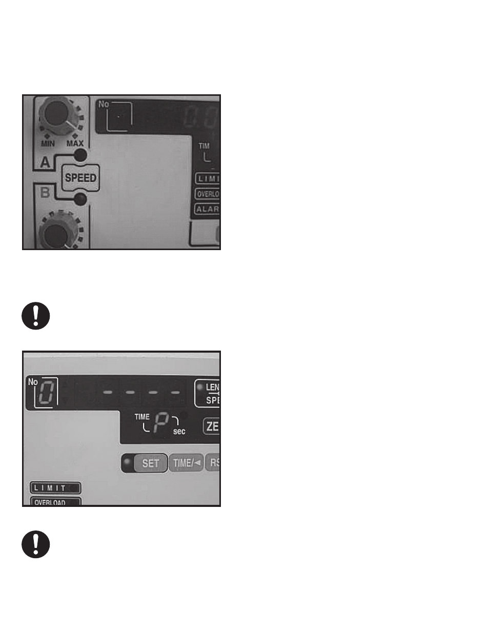
set point 1. Ensure that the correct LED indicator for “Speed A” or “Speed B” is illuminated so that
the test stand will travel at the intended speed. (see photo)
Using the “PUSH” or “PULL” button, move the
test stand force gauge platform to position 1.
Press the “SET” key. (Note: If a programmed
force limit is detected by the force gauge, the
test stand will not move through the entire
programmed distance and the test stand will
then return to set point zero.)
The display in the “No” box shows “2”, and the
“LENGTH, SPEED, CYCLE” display shows “----
”. The “2” designates the next position of a cycle
that the test stand will move to. This position
is defi ned as set point 2. Using the “PUSH” or
“PULL” and the “SPEED A” or “SPEED B” control
knobs move the force gauge to position 2
Shown point zero ready to accept entry.
Use Push and Pull button to increment and
decrement value.
If no more steps are desired, press the “SET”
key while the “LENGTH, SPEED, CYCLE”
display shows “----” to fi nish programming the
test stand.
Speed knob A and B. Desired speed can be
selected by pressing the “Speed” Button.
NOTE: If the programmed force limit is detected by the force gauge the test stand will not move the entire
programmed distance and the force gauge will return to set point zero.
It is not necessary to provide entries for all 5 set points. The test stand will work with one set point. If more
than two set points are entered and a change in the value of the second set point is required, re-enter the set
points for both entries. The distances (length) for the test stand program are accumulative, and dependent
on the previous set point.