Checkline DT-361 User Manual
Page 32
32
External pulse input
4.7.2
Connect the unit to external devices (sensors, etc.) to allow the strobe to emit light using the pulse
signal from those devices in the external trigger mode.
(For details, refer to 4.4 External synchronous emission)
Available input frequency
: Available measurement range 40 to 35,000fpm
Available delay emission range 60 to 10,000fpm
Available input pulse
: Hi 2.5 to 12V
: Lo 0 to 0.5V
Available input pulse width : 50 μs or more
Available delay setting angle : 0º to 359º, available to set by 1º
Available delay setting time : 0 to 999 (max.) ms, available to set by 1 ms
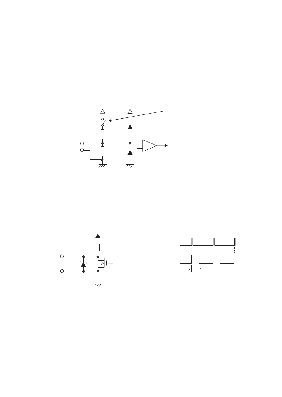
[Input circuit]
External
I/O connector
5pin
6pin
12V
Go to the input circuit
(insulated by photo coupler)
10kΩ
4.7k
10kΩ
12V
Switch in function mode 4
External trigger pulse output
4.7.3
Output the pulse to external devices simultaneously with emission while emission is performed in
the internal oscillation mode or external trigger mode.
A delay of approximately 30 μs caused by the internal circuit exists.
Output circuit specification : 12 V voltage output
Output pulse width
: Approx. 200 μs
[Output circuit]
[Output timing]
(36V)
External
I/O connector
3pin
4pin
12V
4.7kΩ
Emission
External
pulse output
Approx. 200 μs
Inside DT-361/365