Checkline DT-361 User Manual
Page 19
19
How to set the delay
4.4.3.1
The delay angle from the pulse input to emission can be set by 0.1º within the range between 1º
and 359º by setting one cycle of the external pulse to 360º. Measure the external pulse frequency
per cycle, and calculate the delay angle based on the measured frequency to perform the delay
emission. Since a delay of approximately 30 μs always exists for the internal calculation, the actual
delay time is calculated as follows:
Delay setting angle
× External pulse cycle + Approximately 30 μs
360°
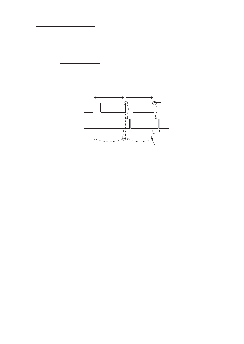
[Example 1] When setting the input frequency to 10 Hz (600 fpm), trigger edge to rising, and
delay angle to 36º
External pulse
(Pulse entered from an
external device to DT-361/365)
Strobe emission
100ms 360º
10ms 36º
Frequency
calculation
Delay
emission
Frequency
calculation
100ms 360º
10ms 36º
Delay
emission
* When the delay unit is set to ms in the above example, the delay time can be set within the time range
of less than one cycle input pulse (0 ms to 99 ms).
• Since the delay angle is calculated based on the previously entered pulse cycle, if the external
pulse frequency changes, emission cannot be performed at a precise angle. Also, since the
external pulse cycle becomes shorter than the previous pulse cycle, if the next pulse is entered
before delay angle emission, the delay angle setting will be disabled, and emission is performed
simultaneously* with the external pulse.
•When the delay angle is set to 0º, emission is performed simultaneously with the external pulse.
* Since there is a delay caused by the internal calculation process, the strobe actually emits light in
approximately 30 μs after the external pulse is entered.
Turn the dial to the right to increase the delay angle setting value. Increasing the setting value from
359º will be 0º.