Dip switches, M-control remote control settings on the 6416y2 – Aviom 6416Y2 User Manual
Page 60
50
m
-
control
DIP Switches
When programming a 6416Y2 card manually, DIP switches in block SW3 allow the user to choose a specific Pro64
channel/Slot range to control (in groups of 16 channels) as well as the total number of Pro64 channels available
for remote control (subject to the limits of the host console’s expansion capability as mentioned previously.)
This allows multiple consoles to be used in the same Pro64 network, each with unique m‑control settings. These
settings can be changed from a PC by using Pro64 Network Manager.
The total number of channels that a 6416Y2 A‑Net card can send to or receive from a Yamaha host device is also
affected by the sample rate being used. In Yamaha’s MY16 mode (used for 44.1/48kHz sample rates), each 6416Y2
card (and its MY expansion card slot) will be associated with two virtual HA devices—16 channels total. In MY8
mode (88.2/96kHz), each 6416Y2 card installed is associated with a single virtual HA device (8 channels). Not all
sample rates are available on every Yamaha console. Refer to the table above.
Only active Pro64 preamp channels can be controlled remotely; any remote control commands sent from a
Yamaha console to inactive 6416m channels will be ignored. As with the RCI/MCS, the 6416Y2 must be set to the
same Control Group as all 6416m Mic Input Modules to be controlled. The Control Group is assigned using the
internal DIP switches on the 6416Y2 card, and a 6416Y2 card must always be part of a Control Group when using
m‑control; it cannot be set to the “off” Control Group as the 6416m and RCI can.
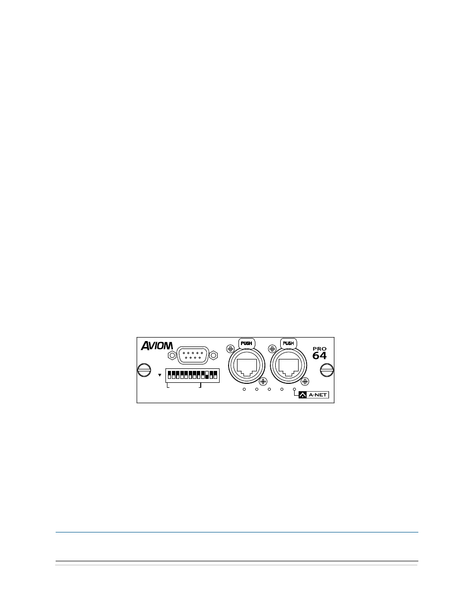
m-control Remote Control Settings on the 6416Y2
On the front panel of the 6416Y2 card, set DIP switch #10 to the down position to enable m‑control.
Note that even though multiple 6416Y2 cards can be installed in a Yamaha digital device, only one 6416Y2 card
needs to be set to provide remote control messages from the Yamaha device to the Pro64 network. This card
must be installed in the Yamaha device’s expansion slot #1.
RS–232/422
STEREO LINK
6416
Y2
B
A
ON
CTL
CLK
AUTO
ERR
1 2 3 4 5 6 7 8 9 10 11 12
DIP switch #10 in the down position enables console remote control. (DIP switch handles are shown in black.)
Once remote control is enabled, DIP switch block SW3 is used to configure the m‑control remote control
parameters. The A‑Net Slots that are controllable from a particular Yamaha device are defined by the Channel/Slot
Control DIP switches, which are DIP switches number 1 through 4 on block SW3. This feature allows the user to
choose a specific range of the Pro64 network to control from a particular console (also available from within
Pro64 Network Manager).
Any combination of the Pro64 Slot banks can be activated for control. Channel/Slot Control settings are
independent of the Slot ranges used for A‑Net Transmit and A‑Net Receive as well as for the individual channel
activation settings for audio being sent from the console into the Pro64 network; both groups of settings must
be properly configured for successful console‑based control.
P
N
ote
:
The actual number of remote controllable channels is determined by the expansion capability of the
particular Yamaha console being used.