Dip switch locations, Sw7, front of card – Aviom 6416Y2 User Manual
Page 36
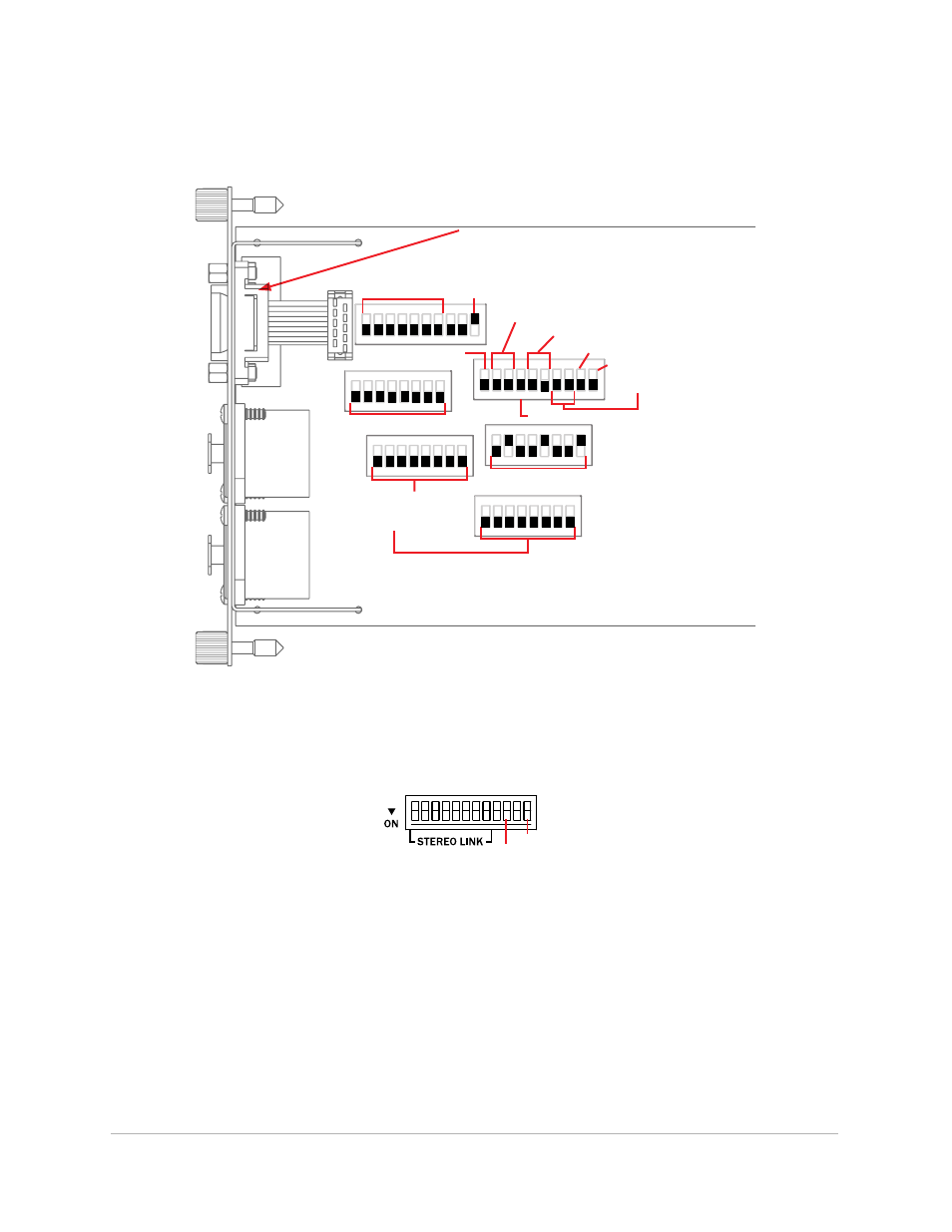
DIP Switch Locations
This diagram shows the locations of the 6416Y2 DIP switches.
ON
ON
ON
ON
ON
ON
SW7
SW8
SW3
SW9
SW4
SW1
SW2
1 2 3 4 5 6 7 8 9 10
1 2 3 4 5 6 7 8 9 10
1 2 3 4 5 6 7 8
1 2 3 4 5 6 7 8
1 2 3 4 5 6 7 8
1 2 3 4 5 6 7 8
Transmit Slots
(from console)
Transmit Port
Control Source
Managed Mode
Front Panel
Receive Slots
(to console)
Receive Port
MY16/MY8
VDC
Channel Activation (1-8)
Channel Activation (9-16)
Remote Control
Mode
VDC
The 6416Y2 DIP switches; the arrow indicates SW7, on the front of the card, shown below.
(DIP switch handles are indicated in black.)
Control
Master
SW7, Front of Card
Remote
Control
26
dIP s
wItches