Vdc slot assignments - front panel vdc port, My8 and my16 mode operation – Aviom 6416Y2 User Manual
Page 44
VDC Slot Assignments - Front Panel VDC Port
Switches 5, 6, and 7 are used to assign Virtual Data Cable Slots for the front panel RS‑232/422 VDC port. The
following table lists the possible settings for the 14 VDC Slot assignments available in a Pro64 network.
RS‑232/422 communication always requires a pair of Virtual Data Cable Slots; this pair must always be an odd‑
even combination of VDCs. The default setting for DIP switch 1 in block SW8 is RS‑232.
VDC Slot Assignments for the Front Panel VDC Port ‑ Switch Block SW8
VDC Slot Pair
DIP Switch 5
DIP Switch 6
DIP Switch 7
OFF
off
off
off
1 & 2
on
off
off
3 & 4
off
on
off
5 & 6
on
on
off
7 & 8
off
off
on
9 & 10
on
off
on
11 & 12
off
on
on
13 & 14
on
on
on
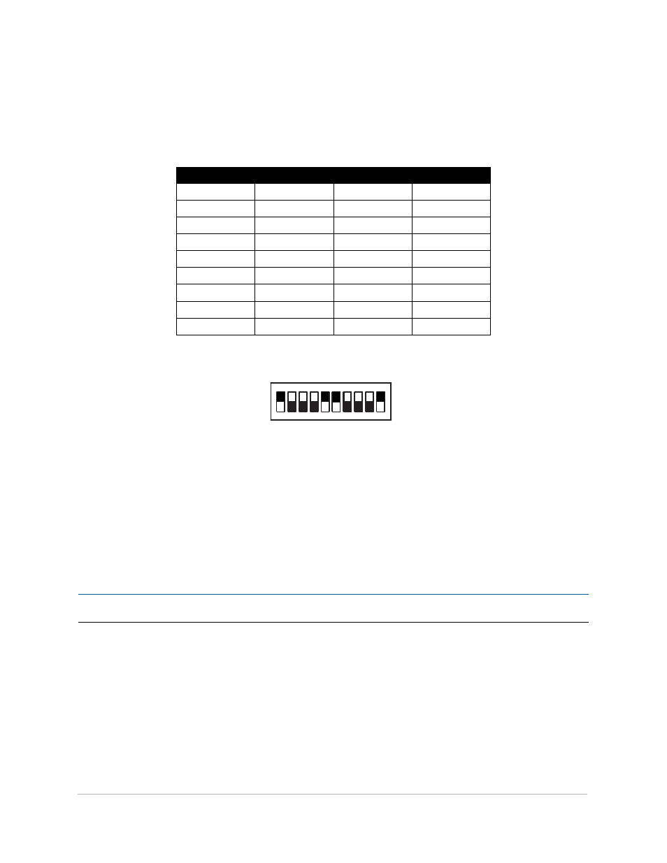
The individual DIP switches on block SW8 are numbered 1‑10, from left to right.
ON
ON
ON
ON
ON
ON
SW7
SW8
SW3
SW9
SW4
SW1
SW2
1 2 3 4 5 6 7 8 9 10
1 2 3 4 5 6 7 8 9 10
1 2 3 4 5 6 7 8
1 2 3 4 5 6 7 8
1 2 3 4 5 6 7 8
1 2 3 4 5 6 7 8
This example shows block SW8 with an RS-422 port assigned to VDC Slot 5-6 on a card set for MY16 mode (using switch #10).
Switch handles are shown in black.
MY8 and MY16 Mode Operation
Yamaha digital products can operate in either 8‑channel or 16‑channel modes (called MY8 and MY16 respectively).
MY8 Mode allows eight channels of I/O per expansion card at sample rates up to 96kHz. MY16 Mode operation
allows up to 16 channels per expansion card at the 44.1/48kHz sample rate. The 6416Y2 can be set to accommodate
these modes by setting DIP switch 10.
P
N
ote
:
This switch cannot be controlled from within the Pro64 Network Manager software.
34
dIP s
wItch
f
unctIons