Front panel features, Thumb screws, Rs-232/422 port – Aviom 6416Y2 User Manual
Page 31: Thumb screws rs‑232/422 port, Omponents
6416Y2 c
ard
c
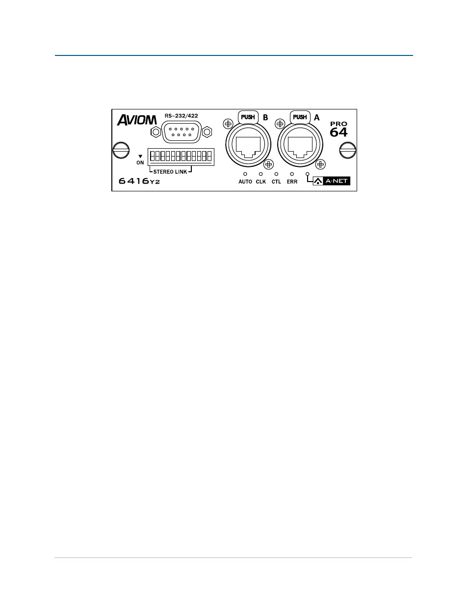
omPoNeNts
Thumb Screws
1.
2. RS‑232/422 DB9 connector
3. DIP Switches 1‑8 – Stereo Link
DIP Switches 9‑12 – system control
4.
Locking
5.
EtherCon RJ45 A‑Net connections
Auto Mode,
6.
Clock Master (CLK), Control Master (CTL), and Error (ERR) LEDs
7. A‑Net active LED
Front Panel Features
This section describes the features and functions of the front panel of the 6416Y2 A‑Net card interface.
Thumb Screws
The two permanently attached thumb screws on the 6416Y2 card are used to secure the card to an MY expansion
slot in the Yamaha device. Always make sure that both thumb screws are firmly attached when using or
transporting the Yamaha device with a 6416Y2 installed.
RS-232/422 Port
The nine‑pin DB9 RS‑232/422 port can be configured to send/receive control data from the Yamaha interface or
from the Pro64 Virtual Data Cables. Selection of RS‑232 or RS‑422 and baud rate configuration is done via the DIP
switches on the circuit board of the 6416Y2 card.
Each type of control data communication—RS‑232 and RS‑422—requires a unique cable. RS‑232 requires a
null modem cable; RS‑422 requires a straight‑through cable. Cable pinouts for RS‑232 and RS‑422 are available
elsewhere in this document.
21
c
ard
c
omPonents