Configuration notes – Aviom AN-16/i User Manual
Page 43
35
AN-16/
i
i
Nput
M
odule
u
ser
G
uide
remaining three AN‑16/i Input Modules to ports B, C, and D.
On the Receive side
3.
Connect a Cat‑5e cable from port A on the second System
4.
Bridge to the A‑Net In jack on the first AN‑16/o Output
Module.
Repeat this process to connect ports B, C, and D to the
5.
remaining AN‑16/o Output Modules.
Connect the two sides of the system by running a Cat‑5e
6.
cable (with or without an EtherCon connector) between
the two A‑Net Bridge jacks on the System Bridges.
To use other configurations, simply move any pair of AN‑16/i and AN‑16/o
units.
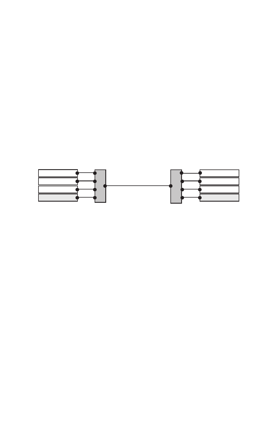
In the following example, the devices connected to port D on the System
Bridge have been swapped to create a 48 x 16 system.
AN-16/i
AN-16/i
AN-16/i
AN-16/o
AN-16/o
AN-16/o
AN-16/o
AN-16/i
A-Net Out
A-Net In
A
B
C
D
A
B
C
D
Bridge
System Bridge
System Bridge
A 48 x 16 system is created by exchanging the units connected to port D on the
System Bridge.
Remember, the total cable length between A‑Net devices should not exceed
500 feet, 150 meters. Cables used to connect A‑Net devices to the System
Bridge are included in this calculation.
Configuration Notes
When configuring 64‑channel systems that send data in both directions,
Aviom suggests the following module combinations. While not mandatory,
these suggestions are made to accommodate the standard wiring practices
that Ethernet uses. (Aviom’s A‑Net technology is based on Ethernet.) Some
wire pairs in a standard Ethernet cable are not next to each other inside the
jacket of the cable. This can account for slightly higher data errors in rare
cases.
The configuration recommendations apply to systems configured as
16 x 48 and 32 x 32, not those sending data in only one direction. The module
combinations are applicable especially when using long cable runs.
For 16 x 48 (or 48 x 16) configurations, place the three similar modules