Connecting the system bridge – Aviom AN-16/i User Manual
Page 42
34
AN-16/
i
i
Nput
M
odule
u
ser
G
uide
These accept standard Cat‑5e cables. These jacks will always connect to an
Pro16 A‑Net compatible product.
The connection labeled A-Net Bridge will always connect to another System
Bridge’s A‑Net Bridge connector.
Connecting the System Bridge
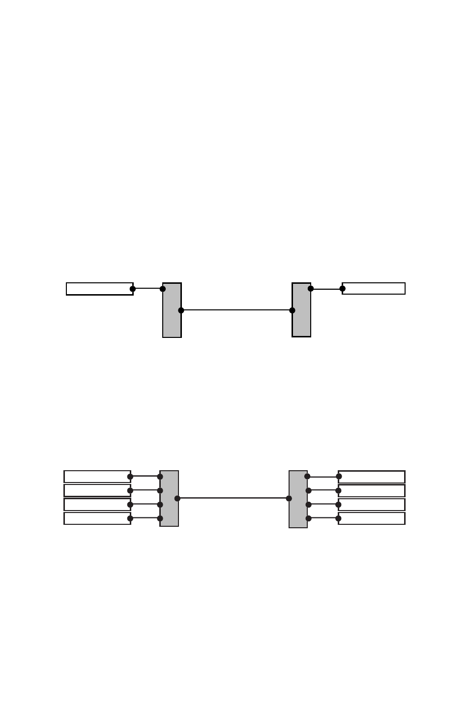
Adding a System Bridge to an audio network is quite simple. Two System
Bridges are needed to create a network. The four A‑Net connectors (labeled
A, B, C, and D) on one side of the network are directly related to the A, B, C,
and D connectors on the other side of the network. That is, if you patch an
AN‑16/i Input Module into port “A” on one side of a System Bridge, an AN‑
16/o Output Module would be connected to port “A” on the other side of the
System Bridge. See the following diagram.
AN-16/i
AN-16/o
A-Net Out
A-Net In
A
B
C
D
A
B
C
D
Bridge
System Bridge
System Bridge
This diagram shows the relationship of the A, B, C, and D ports on the AN-16SB.
A complete network using four units per side follows the same pattern.
An AN‑16/i Input Module connected to port B on one side of the network
connects to an AN‑16/o Output Module via port B on the other side of the
network. The same goes for ports C and D, as seen in the following diagram.
AN-16/i
AN-16/i
AN-16/i
AN-16/i
AN-16/o
AN-16/o
AN-16/o
AN-16/o
AN-16SB
AN-16SB
A-Net Out
A-Net In
A
B
C
D
A
B
C
D
Bridge
A-Net ports A, B, C, and D are shown connected in a 64 x 0 network configuration
To connect a 64 channel network (64 x 0):
On the Send side
Connect a Cat‑5e cable from the A‑Net Out of the first
1.
AN‑16/i to port A on the first System Bridge
Repeat this process to connect the A‑Net out from the
2.