An-16/i v.2 front panel – Aviom AN-16/i v.2 User Manual
Page 17
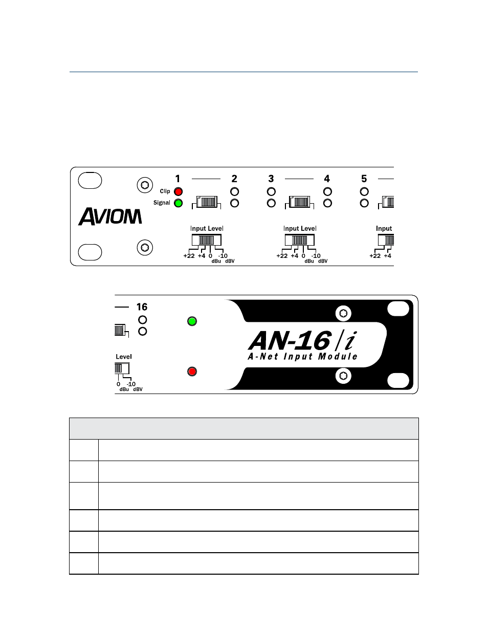
AN-16/i v.2 Front Panel
Use the following diagrams to become familiar with the components of the front and rear
panels of the AN-16/i v.2 Input Module.
Function
1
Clip LED, red – Lights when the audio signal is 3dB below full scale (0dB)
2
Signal Present LED, green – Lights to show that an audio signal is present on a channel
3
Stereo Link Switch – In the left position, each channel is mono; in the right position, the
channels are linked as a stereo pair
4
Input Level Switch – Selects one of four available operating levels; selectable for each
channel pair
5
A-Net In LED, green – Indicates that the AN-16/i v.2 is receiving a valid A-Net signal from
another Pro16 device
6
Power LED, red – Indicates that the AN-16/i v.2 is powered on
A-Net In
Power
v.2
Mono
Stereo
Mono
Stereo
Mono
Stereo
Mono
Stereo
Mono
Stereo
Mono
Stereo
Mono
Stereo
Mono
Stereo
A-Net In
Power
v.2
Mono
Stereo
Mono
Stereo
Mono
Stereo
Mono
Stereo
Mono
Stereo
Mono
Stereo
Mono
Stereo
Mono
Stereo
9
AN-16/
i
v
.2 i
Nput
M
odule
u
ser
G
uide