Sas-100-cm ceiling mount u-bracket application, Installation instructions – Adaptive Technologies SAS-100-CM User Manual
Page 3
© 2004 Allen Products Company Incorporated, Signal Hill, CA 90755 USA (562) 424-1100 07/04
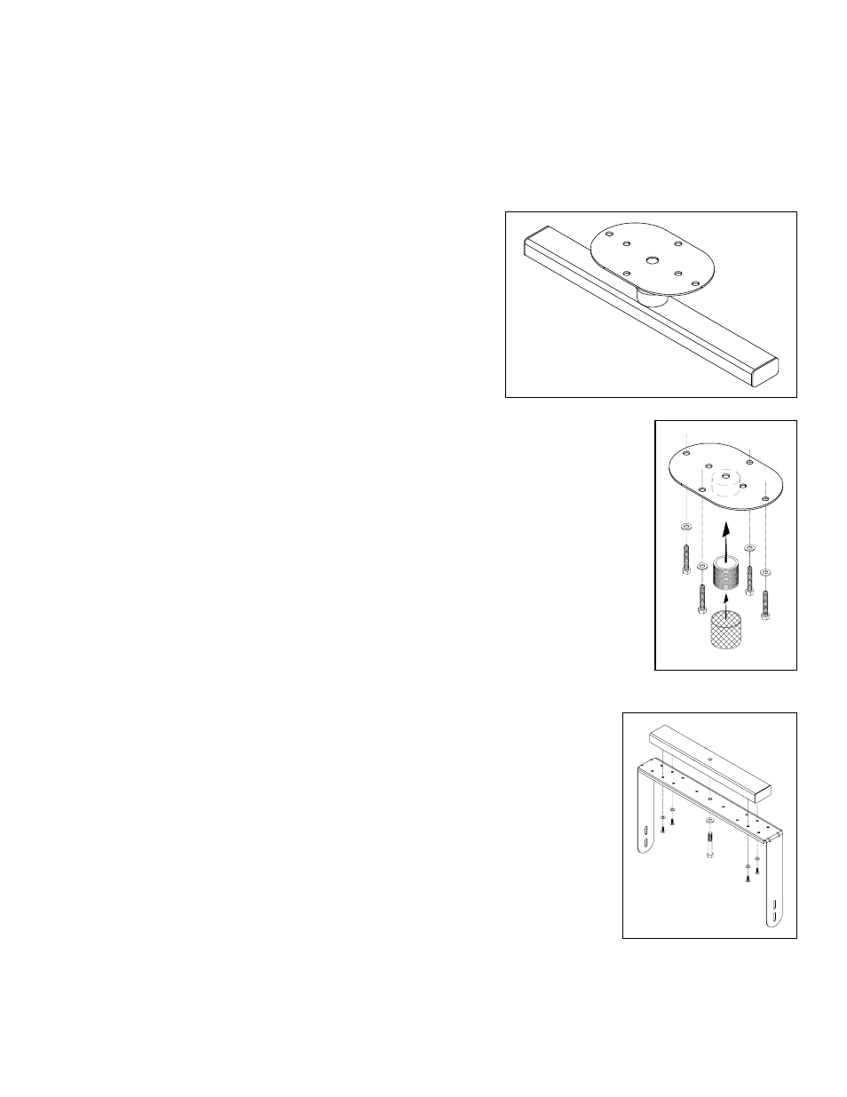
Figure 1
Figure 2
SAS-100-CM Ceiling Mount
U-Bracket Application
Installation Instructions
Thank you for selecting the Steerable SAS-100-CM
Ceiling Mount. This
universal ceiling speaker mount provides a 360° pan angle adjustment.
It suspends and precisely aims speakers equipped with rigging and
mounting points from ceilings and other structural overhead surfaces.
Important:
Mounting and rigging video equipment requires experienced
professionals.
Improperly installed video equipment can result
in property damage, personal injury, death and/or liability to
the installing contractor.
Do not install if in doubt about the integrity
of the mounting structure.
Caution:
Due to the wide variety of building structures, materials and mounting methods, these
instructions assume that the installing contractor/installer will exercise good judgment in
selecting the proper mounting area hardware.
As a guide, the installation, when completed should be capable of supporting at least 5 times
the actual applied load.
Follow these instructions for the most efficient and safest mounting results.
Step 1. Install Ceiling Plate:
Secure the ceiling mount above a structurally sound horizontal grid. Be sure the ceiling plate
center is level and directly above your desired suspension point (Figure 1).
If you have doubts
about the integrity of the structure you are mounting to, or you are not sure about the proper
hardware to use, consult your local hardware specialist.
Step 2. Install Extension coupler:
Thread the extension coupling into the threaded hub of the ceiling plate then place the wire
mesh cover around it (Figure 1).
Step 3. Attach Selected U-Bracket to Cross Arm:
Attach the selected U-Bracket to the cross arm using four 1/4-20 screws, 1/4” flat washers
and locknuts. Do not tighten. Make sure the 1/2” diameter center hole of the U-Bracket
clears the center hole of the cross arm (figure 2).
Step 4. Assemble Hubcap to Cross Arm:
Attach the hubcap to the cross bar/U-bracket assembly, first with the 1/2 hex bolt from
under the U-Bracket then the washers and nut (Figure 3). Tighten permanently but do not
over tighten. Insert cotter pin into the hole of the 1/2” bolt then secure the ends around
the bolt. Tighten the U-bracket’s 1/4-20 screws permanently (Figure 3).
Step 5. Join Cross Arm to Ceiling Plate:
Align and hand thread the hubcap of the cross arm assembly over the extension coupling
inside the ceiling plate. Use a pipe wrench to tighten connection permanently (Figure 4).
Slip mesh over hub.
Step 6. Attach Speaker:
Attach Speaker to selected U-Bracket
(See U-bracket Instruction sheet for speaker installation).