Adaptive Technologies PM-BAND-20S User Manual
Polestar, Pm-band-20s
© 2008 Allen Products Company, Signal Hill, CA 90755 USA (562) 424-1100
021408
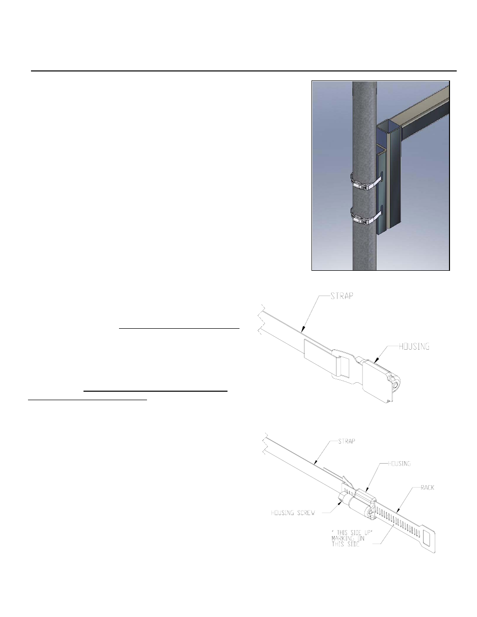
Figure 1:
Figure 2:
PoleStar
TM
PM-BAND-20S
Band Kit for 2” to 6” Dia. Poles and Columns
Installation Instructions
T
hank you for choosing the PoleStar
TM
PM-Band-20S Kit. This all weather, stainless steel
banding strap is designed to attach the PoleStar
TM
Pole Adapters to 2” dia. to 6” dia. poles.
Important:
Mounting overhead system requires experienced professionals. Improperly installed
equipment can result in property damage, personal injury, death and/or liability to the
installing contractor. Do not install if in doubt about the integrity of the mounting structure.
Caution: Due to the wide variety of mounting structures, environments, materials and mounting
methods, these instructions assume that the installing contractor will exercise good judgment in
selecting the proper mounting area and hardware.
Follow these instructions for the most efficient and safest mounting results. Do not
exceed the working load limit of 150 lbs/68 kg.
Caution: Use care in uncoiling and applying strap.
Package Contents:
Qty
Description
2 pcs
PM-BAND-20S Housing
2 pcs
PM-BAND-20S Racks
2 pcs
PM-BAND-20S 20” long banding strap
1 pc
Instruction Sheet
Step 1
Insert one end of the strap into the rectangular slot of the housing then fold
at least one inch long or longer (a longer fold creates a more effective lock)
then flatten band using thumb to form a hook. The folded end should be on
the opposite side of the housing’s screw head (Figure 1).
Step 2
Insert the end of the rack into the housing and rotate screw head clockwise
using a screw driver until 3/4” of the rack comes out on the other end of the
housing (Figure 2). MAKE SURE THAT THE WORD “THIS SIDE UP”
WRITTEN ON THE RACK FACING OUT.
Step 3
Insert the other end of the band through the slots of the PM-MOUNT-
6DOWN and out on the other side. Wrap the band snugly around the pole
until the end reaches rectangular slot of the rack (Figure 3).
Step 4
Measure, mark and cut the band at least one inch beyond the first
serration of the rack, then bend at least a one inch hook toward underside
of band (Figure 4 & 5).
Step 5
Insert the hook into the rectangular slot of the rack, if necessary loosen the
rack from the housing. Flatten band with thumb to form a clamp (Figure 5).