Adaptive Technologies SAS-100-CM User Manual
Page 2
© 2004 Allen Products Company Incorporated, Signal Hill, CA 90755 USA (562) 424-1100 07/04
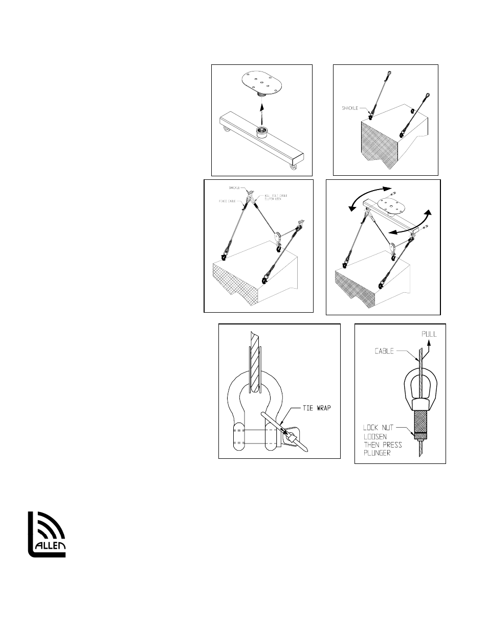
Figure 4
Figure 5
Figure 6
Figure 7
Figure 8
Figure 9
Step 6. Prepare Loudspeaker:
Attach eyebolts, fly track or required other
attachments to the speaker cabinet (Figure 5). If
using the optional Adjustable Tilt Cable Kit,
see
Adjustable Tilt Cable Kit data sheet for kit
selection, methods of attachment and aiming.
Step 7. Install Selected Fixed Cables:
Identify the fixed cables from the selected
Adjustable Tilt Cable Kit (Ordered separately).
Attach one (1) fixed cable to each front
attachment point of the speaker using the 5/16”
shackles (Figure 5). Secure the screw pin to the
shackle using the included cable tie to prevent
the pin from rotating out (Figure 8).
Step 8. Install Adjustable Tilt Cable:
Capture the eye of the pulley of the adjustable
tilt cable kit to the back attachment point of
the speaker using the 1/4” shackle (Figure 6).
Secure the pin to the shackle using the
included cable tie to prevent the pin from
rotating out (Figure 8).
Step 9. Suspend the Speaker from the
Cross Arm:
Using a 5/6” shackle, attach the clutch lock eye
of the adjustable cable and one fixed cable to
one eyebolt of the cross arm. Attach the other end
of the adjustable cable and the other fixed cable to
the other cross arm eyebolt with a 5/16” shackle
(Figure 6). Fully tighten shackle pins and secure
with the included tie wraps (Figure 8).
Step 10. Adjust the Pan Angle:
Hold both ends of the cross bar then slightly turn
horizontally (clockwise or counter clockwise) until
desired direction is achieved (Figure 7).
Step 11. Adjust the Tilt Angle:
Loosen the lock nut on the clutch lock halfway then
pull the free end of the adjustable tilt cable up
while supporting the weight of the speaker until
desired tilt angle is achieved. Tighten lock nut to secure tilt angle. To release tilt angle, loosen the locknut halfway and
depress plunger while supporting the weight of the speaker until desired tilt angle is achieved then release the plunger
(Figure 9).
Figure 2
Allen Products Company Inc.
1635 E. Burnett Street
Signal Hill, CA 90755 USA
Tel: (562) 424-1100 Fax: (562) 424-3520
Web Site: www.allenproducts.com