Adaptive Technologies MM-120-BTM User Manual
Page 2
© 2004 Allen Products Co., Inc. Signal Hill, CA 90755
(562) 424-1100 Rev. 01-101408
Figure 2
Step 3:
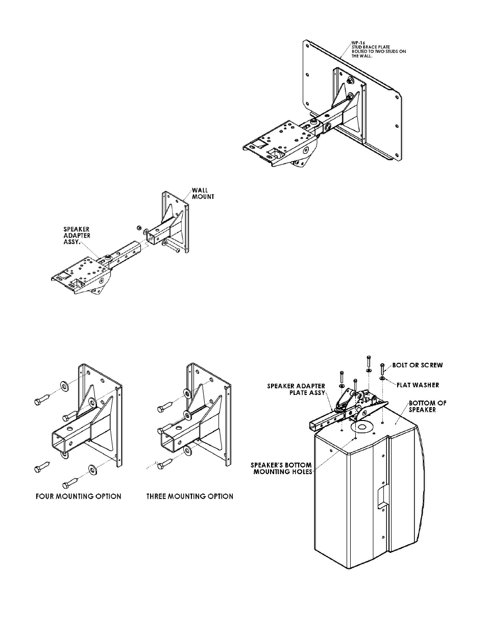
Mount the Wall Mount plate to the selected location using the
optional stud brace plate or directly to the wall. Make sure that
the wall is supported and able to support 5 times the weight of
the speaker. Use a backing plate or plywood if necessary
(Figure 1 and 4).
Step 4:
Attach the adapter plate support arm assembly to the
appropriate bottom mounting holes of the loudspeaker using
the manufacturer’s suggested screws and washers. Tighten
these fasteners permanently (Figure 5). If threaded mounting
points are not included in the speaker, consult the
manufacturer for proper mounting procedures.
Step 5:
Lift speaker with the mount attached up to the wall mounting plate and
insert the support arm into the tube of the wall mounting plate (Figure
6). Select which hole to use from the support arm then line up the
support arm’s selected hole with the wall mounting plate’s hole and
insert the 3/8” x 2 1/2” tap bolt. Permanently secure with 3/8” flat
washer and nut (Figure 6).
Note:
If wiring is coming from the wall mount’s tube, feed the wire first to the
support arm’s tube and out from its upper hole or at the end of the
support arm, before inserting the support arm to the wall mount’s tube.
Step 6: Setting the pan angle
Rotate the speaker horizontally, right or left, until it is aimed
in the desired direction. Permanently tighten the socket head
screw at the support arm with a 5/16” hex wrench (Figure 7).
Figure 3
Figure 5
Figure 4