Adaptive Technologies MM-008-BT User Manual
Page 3
©2004 Allen Products Co., Inc. Signal Hill, CA 90755
(562) 424-1100
10/04-rev01
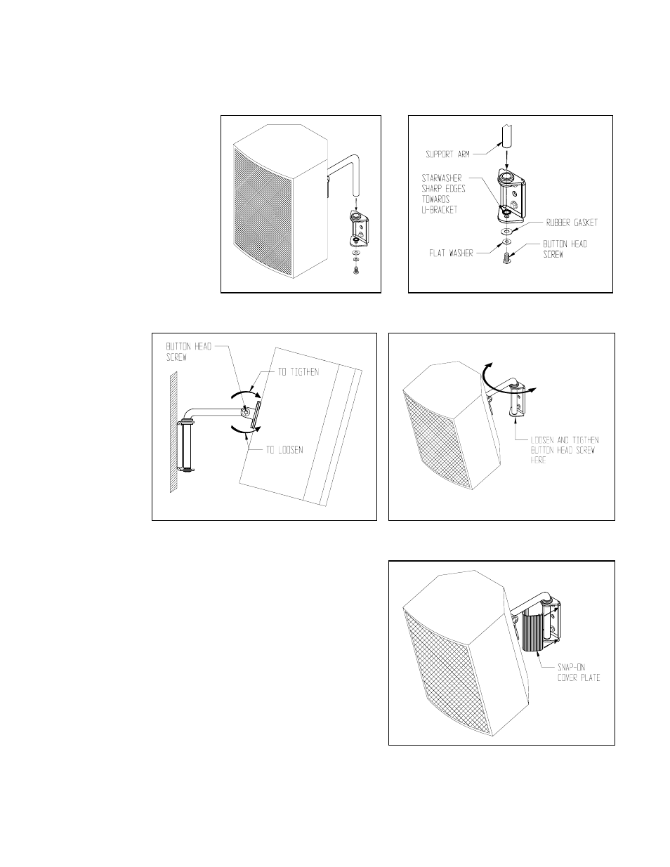
Figure 8
Secure support arm to the mounting plate using the 1/4” button head screw, flat washer, rubber gasket and a star
washer in between the support arm and the mounting plate (Figure 7B). Do not tighten permanently.
Step 6. Setting the tilt angle:
While supporting the speaker’s
weight, loosen the button head
screws at the sides of the
speaker adapter plate (do not
remove). Position the speaker to
the desired tilt angle and hold in
position then re-tighten the
screws. Be sure that the screws
have been tightened
permanently before releasing the
weight of the speaker (Figure 8).
If the tilt angle needs to be
adjusted,
DO NOT PULL ON
SPEAKER
, rather repeat step 6.
Step 7. Setting
the pan angle:
Rotate the
speaker
horizontally right
or left until the
speaker is aimed
in the desired
direction.
Permanently
tighten the button
head screw at the
bottom of the
mounting plate
with a 3/16 hex
wrench (Figure 9).
Step 8. Install Snap on Cover Plate:
Install snap-on cover plate to the wall mounting plate making sure
it snaps and locks into the mounting plate’s return flanges (Figure
10).
Step 9. Recommendation: Install Safety Cable
Attach a safety cable (sold separately) to the mounting surface
(Must be
able to support at least five times the weight of the speaker), then
attach the other end of the safety cable to the speaker. If no attachment is
provided on speaker, consult speaker manufacturer for advice on best
attachment point and method.
Figure 7A
Figure 7B
Figure 9
Figure 10