S-video output connector (s-video out), Rs-232c connector (rs-232c), Rgb/sync output connector (rgb/sync) – Panasonic GP-US532H User Manual
Page 8: 12v dc input terminals (12v dc in), Cautions
Attention! The text in this document has been recognized automatically. To view the original document, you can use the "Original mode".
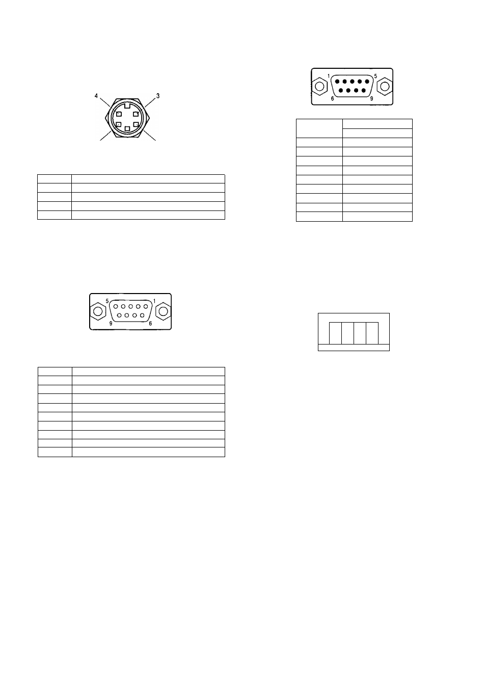
24. S-Video Output Connector (S-VIDEO OUT)
The luminance (Y) and chrominance (C) signals for
VCR or monitor are provided at this connector.
26. RS-232C Connector (RS-232C)
2 1
S-VIDEO OUT (Mini-DIN,4-pin)
Pin No.
Description
1
Y Ground
2
C Ground
3
Y Signal Output {0,714V[p-p](Y level)/75 ii)
4
C Signal Output (0.286V[p-p](Burst Level)/75 £2)
Pin No
Signal
RS-232C
1
Ground
2
TXD
3
RXD
4
DSR
5
Ground
6
DTR
7
CIS
8
RTS
9
Ground
25. RGB/SYNC Output Connector (RGB/SYNC)
The red, green, blue, sync and composite video
signals are provided at this connector.
Note; Refer to the qualified system pasonnel or
system Installers for this connection.
27. 12V DC Input Terminals (12V DC IN)
These terminals accept an external DC po\wer
source supplying nominal power of 12V DC, 0.7A.
RGB/SYNC (D-SUB,9-pin)
g]
Pin No.
Description
1
Ground( GND)
2
Ground (GND)
3
Red (R) Output (0.7V[p-p]/75 ii)
4
Green (G) Output (0.7V[p-p]/75 £2)
5
Blue (B) Output (0.7V[p-p]/75 £2)
6
Composite Video Output (1,0V[p-p]/75 £i)
7
Sync (SYNC) Output (4,0V[p-p] or 0.3V[p-p]/75 £2)
8
Ground (GND)
9
Ground (GND)
Cautions :
1. Connect to 12V DC (11.5 V - 16 V) class 2
power supply only.
2. To prevent fire or electric shock hazard, use a
UL listed wire VW-1, Style 1007 cable for 12 V
DC input terminals.
-
6
-