Camera cable connector (camera), Caution, Rear panel – Panasonic GP-US532H User Manual
Page 7: Gen-tock signal input connector (vbs/hd), Gen-lock signal input connector (vd), Video output connector (video 1,2)
Attention! The text in this document has been recognized automatically. To view the original document, you can use the "Original mode".
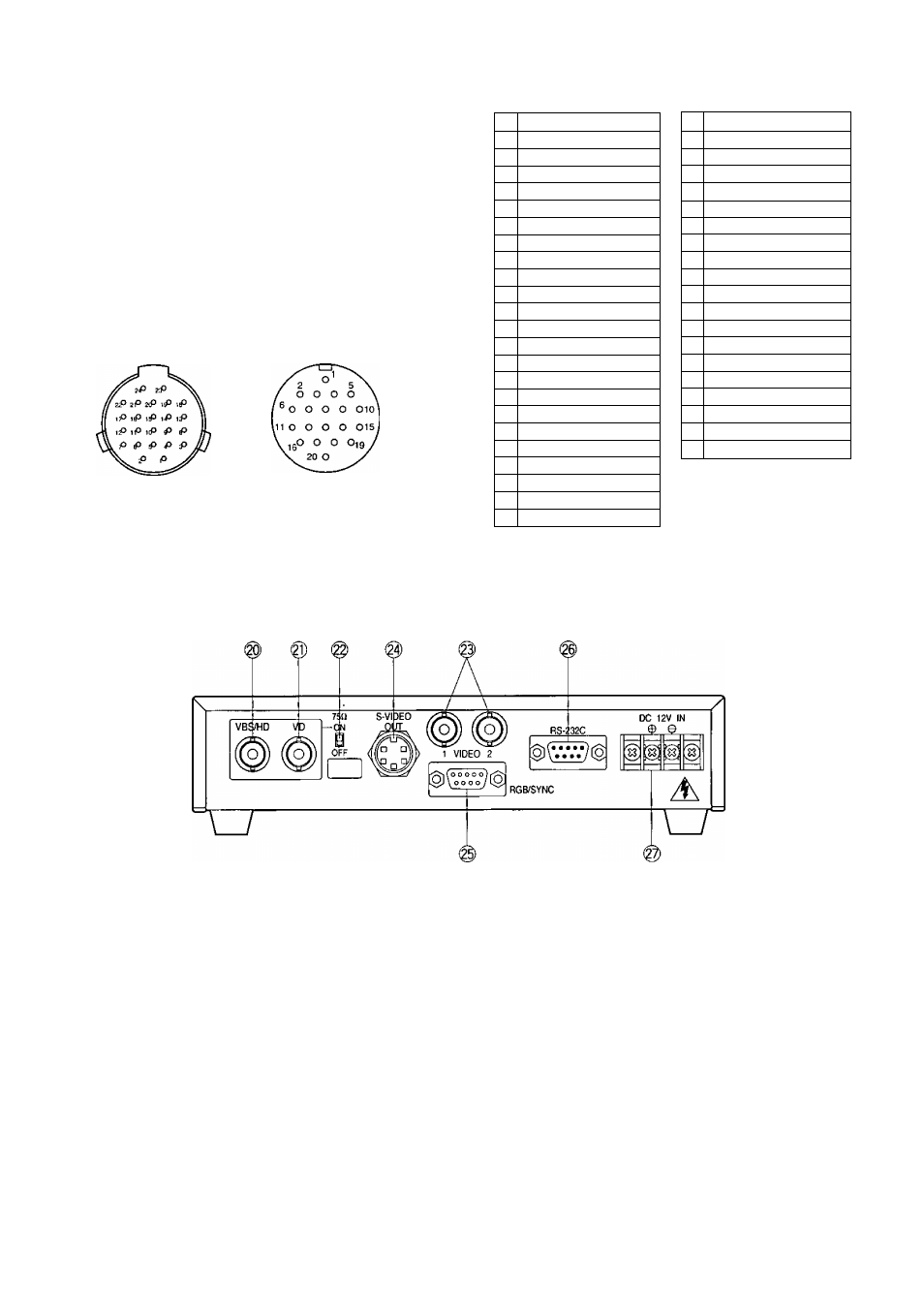
19. Camera Cable Connector (CAMERA)
This 20-pin connector is used for connection with
the cannera head via the optional camera cable
GP-CA522M.
Fasten the camera cable to this connector firmly.
If not, noise may be appeared.
— Caution:---------------------------------------------------
Camera Head Side
Camera Control Unit Side
Connecting or disconnecting camera cable
to/from the camera control unit or camera
head must be done after turning off the
Power of the camera control unit.
For Camera
For ecu
1 -t-15V Input
2 Ground (GND)
3 Chip Select Input
4 +25 Input
5 -9V Input
6 B Signal Output
7 RGB Ground (GND)
8 Serial Data Input
9 Serial Clock Input
10 CCD Select Output
11 G Signal Output
12 R Signal Output
13 VD Input
14 CPOB Output
15 HD Input
16 +9V Input
17 +5V Input
18 PBLK Output
19 Not used
20 Not used
21 Not used
22 Not used
23 28MHz Input
24 Not used
1 Ground (GND)
2 Not used
3 PBLK Input
4 +9V Output
5 -9V Output
6 28MHz Output
7 CPOB Input
8 RGB Ground (GND)
9 +5V Output
10 B Signal Input
11 Serial Clock Output
12 VD Output
13 Chip Select Output
14 +25 Output
15 R Signal Input
16 Serial Data Output
17 HD Output
18 G Signal Input
19 + 15V Output
20 CCD Select Input
[Rear Panel]
20. Gen-tock Signal Input Connector (VBS/HD)
The color video signal of the camera is automatical
ly synchronized to the gen-lock signal (Composite
Signal, Black Burst Signal or Video Sync) when
either signal is supplied to this connector.
The gen-lock signal is used for system reference.
Caution :
If the gen-lock signal is jittery (as in the case of
a VCR playback picture), the camera can not
be synchronized properly.
(External HD and VD Mode)
The horizontal and vertical pulse of the color
video signal is synchronized to the external HD
fed to this connector and external VD fed to the
VD input connector.
21. Gen-Lock Signal Input Connector (VD)
Supply the external vertical drive (VD) pulse to this
connector,
22. Gen-Lock Video 75 ii Termination ON/OFF
Switch (75 a ON/OFF)
When looping through the gen-lock video signal
with BNC "T" adapter, set this switch to OFF. When
not looping through, set this switch to ON,
23. Video Output Connector (VIDEO 1,2)
A 1.0V[p-p]/75 composite video signal is provid
ed at this connector.
-
5
-