S> ® ® ® g, Connection, System connection – Panasonic WVCF20 User Manual
Page 7
Attention! The text in this document has been recognized automatically. To view the original document, you can use the "Original mode".
2-5.Adjust the camera angle to the desired posi
tion.
Refer to the Camera Angle Adjustment on
page 7 for details,
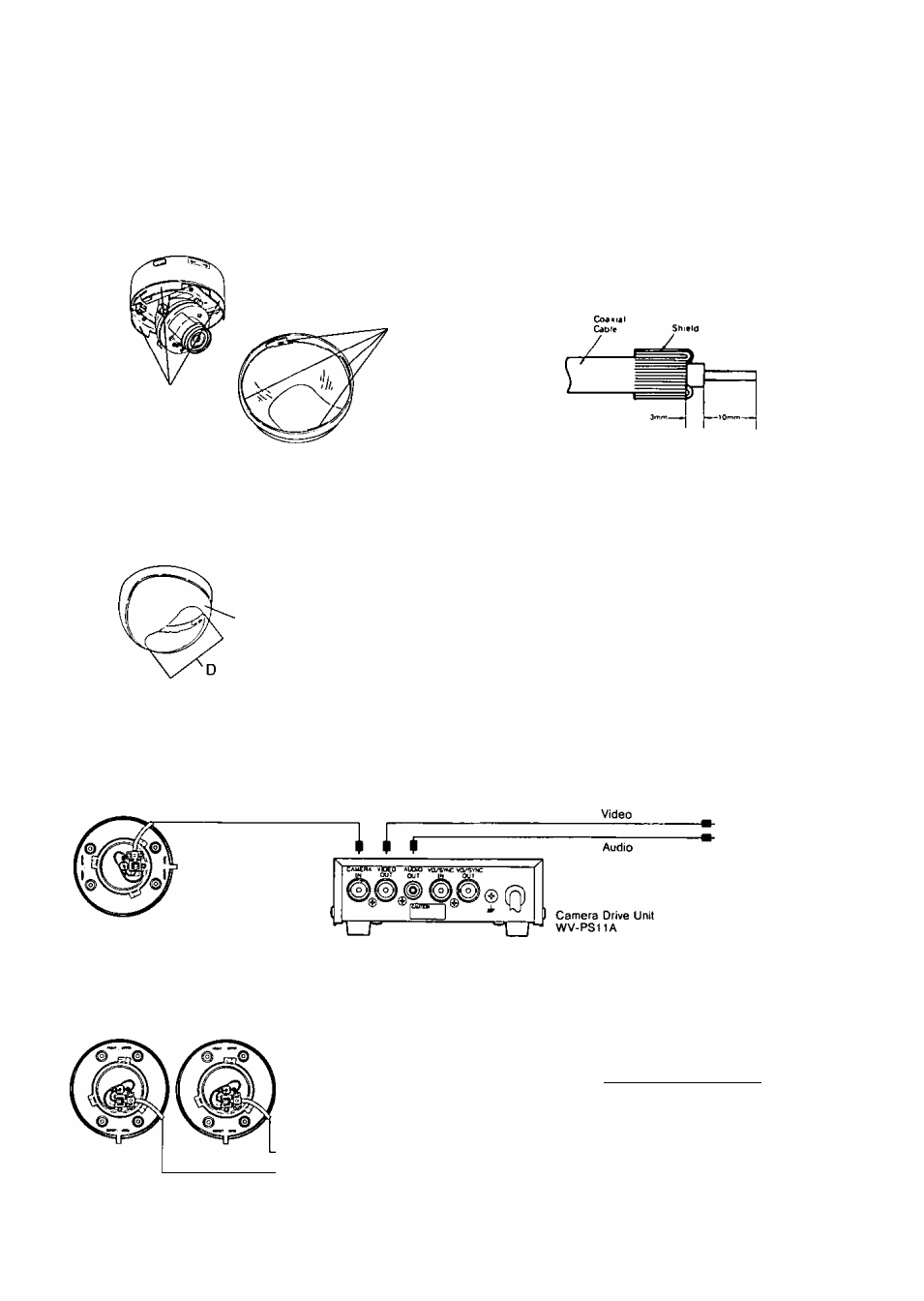
2-6. Match four grooves on the camera to four pro
jections of the Dome Cover,
Projections
grooves
2-7.Reattach the Dome Cover (13) to the camera
by turning this cover clociwise so that the “D"
position is in the front of the Camera Head.
CONNECTION
Preparation :
These connections should be made only by qualified
service personnel or system installers.
Cable Information
Coaxial Cable (Connection for the Video Output
Terminal (19) )
The maximum cable thickness for this camera is
5C-2V (RG-6/U) type.
Note : When assembling the coaxial cable/BNC con
nector, follow connector manufacture’s specific
directions.
Turn Counterclockwise
Dome Cover
SYSTEM CONNECTION
Connection with the optional Camera Drive Unit, WV-PS11A.
Connect a coaxial cable between the Video Output Terminal (19) on this camera and the Camera Input Connector
on the Camera Drive Unit, WV-PS11A.
Connection with the optional monitor WV-CM110A
Connect a coaxial cable between the Video Output Terminal (19) on this camera and the Camera Input Connector
on the monitor.
______
Coaxial Cable (Option)
3C-2V (Maximum Cable length is 200m)
5C-2V (Maximum Cable length is 500m)
jO_ ^
i
S> ® ® ® g> ^ (|^
Video Monitor WV-CM110A
-6-