I 1 ì – Panasonic TX-2103MA User Manual
Page 6
Attention! The text in this document has been recognized automatically. To view the original document, you can use the "Original mode".
■ Signal Connection
The signal connector should be connected as follows according to the type of signal connector
and the signaling system used.
A. When the Signal Connector is 15 Pin Mini D-Sub (In the Case of PS/2 or compatible)
Connect the signal cable to the 15 pin mini D-sub connector of the display unit.
Push the signal connector select switch upwards.
B. When the Signal Connector is a 15 pin D-Sub Connector (In the case of MAC-II)
Convert the 15 pin D-sub connector of the MAC-II to a 15 pin mini D-sub connector using a con
version connector, and then connect it to the 15 pin mini D-sub connector of the display unit.
Push the signal connector select switch upwards.
Check if the change-over connector is connected as shown in the following figure.
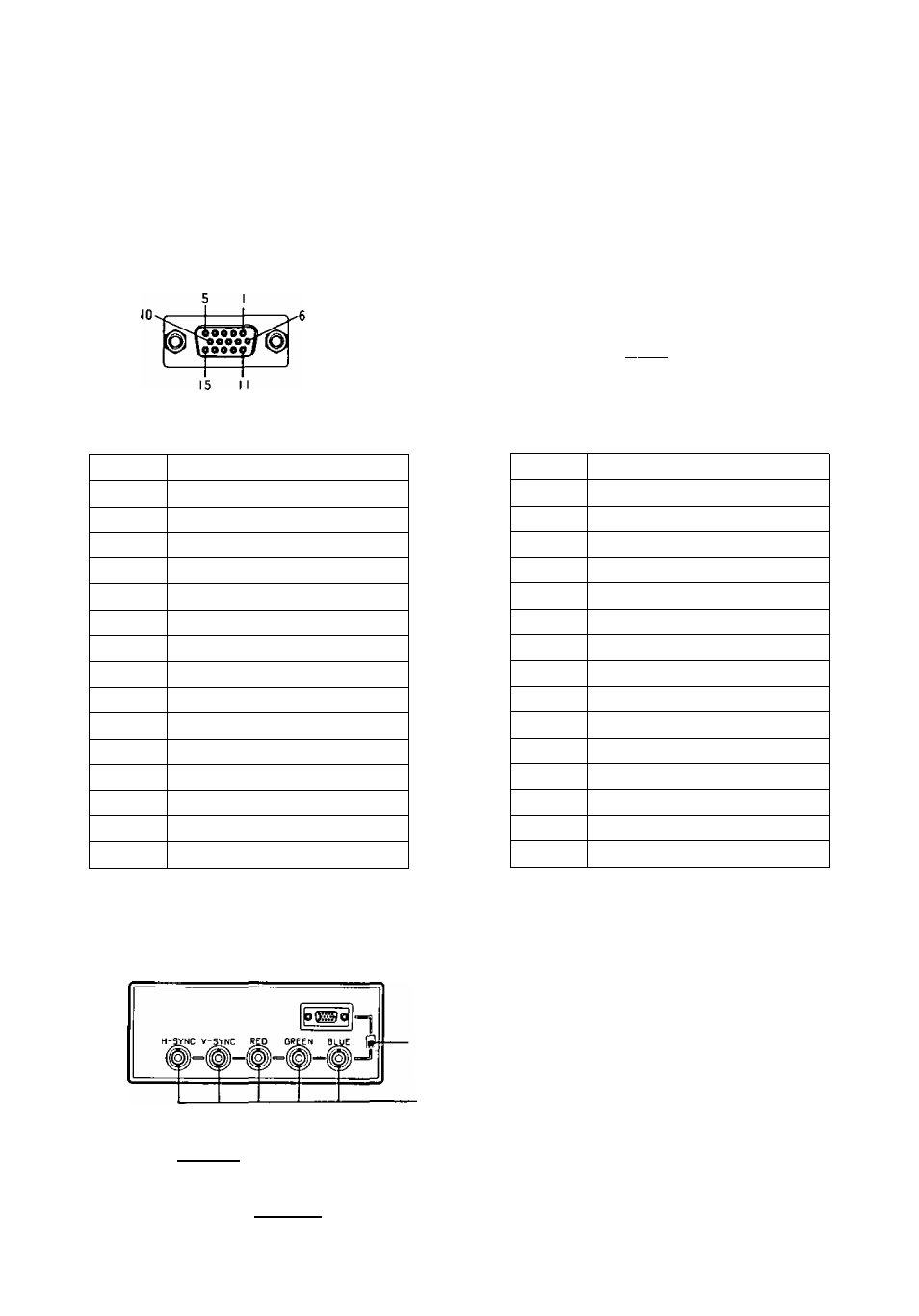
Pin Arrangement of 15 Pin
Mini D-Sub Connector
p fi 3 fi
5
9
Pin Arrangement of 15 pin
D-Sub Connector
Pin No.
Signal name
1
Red video signal
2
Green video signal
3
Blue video signal
4
Ground
5
Space No connection
6
Ground for red video signal
7
Ground for green video signal
8
Ground for blue video signal
9
Space No connection
10
Ground
11
Ground
12
Space No connection
13
Horizontal synchronizing signal
14
Vertical synchronizing signal
15
Space No connection
r
Pin No.
Signal Connector
1
Ground for red video signal
2
Red video signal
3
Composite synchronizing signal
4
Ground for composite synchronizing signal
5
Green video signal
6
Ground for green video signal
7
Space No connection
8
Space No connection
9
Blue video signal
10
Space No connection
11
Space No connection
12
Space No connection
13
Ground for blue video signal
14
Space No connection
15
Space No connection
C. When the Signal Connector is BNC Connector Signal Systems
Push the signal connector select switch downwards.
f
1
M
i 1 Ì
Signal connector select switch
Separate System
Connect the signal cables to RED, GREEN,
BLUE, H-SYNC AND V-SYNC connectors.
Composite System
Connect the signal cable to RED, GREEN, BLUE
and H-SYNC (H/V composite) connectors.
Sync On Green System
Connect the signal cable to RED, GREEN (sync
on green) and BLUE BNC connectors.
- 4 -