B. wiring diagram – Panasonic WJ-SQ508 User Manual
Page 17
Attention! The text in this document has been recognized automatically. To view the original document, you can use the "Original mode".
B. WIRING DIAGRAM
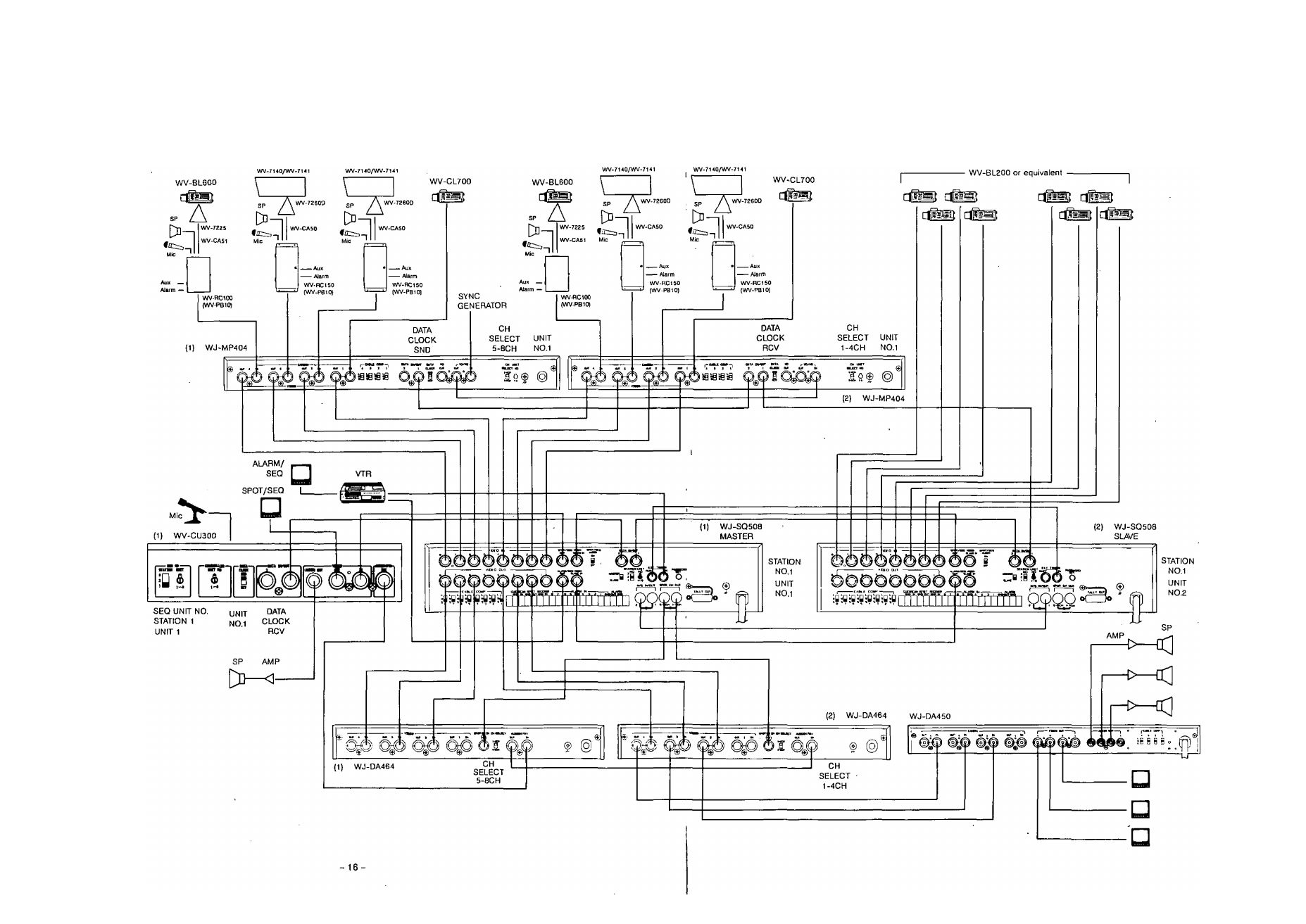
This diagram shows one of examples for the actual wiring
and the selection of the Unit Numbers and switchers. Refer
to "HOW TO SET UR THE UNIT NUMBERS' on page 12 for
setting up the Unit Numbers of WJ-SQ508 and WV-CU300.
Also refer to the operating instructions of each component
for the selection of the switches.
In this example, 16 cameras, 2 Multiplex Units WJ-MP404,
2
Sequential Switchers WJ-SQ508,
2
Audio Mix &
Selectors WJ-DA464,
1
System Controller WV-CU300,
1
AV Demodulator WJ-DA450 and other system components
are used.
Each WJ-MP404 is receiving 3 audio signals and
these signals are multiplexed on the video signals
then transmitted to WV-CU300 and WJ-DA464 through
WJ-SQ508.
Mic signal from WV-CU300 is transmitted to the camera
site through WJ-DA464 and WJ-SQ508.
Two Sequential Switchers WJ-SQ508 are composed
of a master/slave configuration.
/
The
ALARM/SEQ
output
signal
of
the
master
WJ-SQ508 will be supplied to the VTR.
The SPOT/SEQ output picture wilt be supplied from
WV-CU300 to the monitor.
To monitor the sounds of the camera sites, connect
WJ-DA450 to WJ-DA464 as shown in the diagram.