2 9135g interface leds, 3 enable/disable llf or lle, Figure 8. 9135g interface led indicators -8 – CANOGA PERKINS 9135G SNMP Managed Gigabit Ethernet Switch User Manual
Page 16: Table 2. 9135g interface leds -8
EdgeAccess Ethernet Switch
2.7.2 9135G Interface LEDs
Table 2. 9135G Interface LEDs
LED
Status
Description
Tx (Transmit)
Off
No transmit activity
Green
Currrent transmit activity
Red
Transmitter is disabled due to LLF or LLE
Lnk (Link)
Off
The interface has not established an optical link
Green
The interface has an optical link established
Pse (Pause)
Amber
The interface is receiving too much data or too fast
LLF (Link Loss Forward) Off
Link Loss Forward is disabled
Green
Link Loss Forward is enabled
Rx
Off
No receive activity
Green
Current receive activity
Red
Remote
fault
detected
Fdx
Off
Operating as half-duplex
Green
Operating as full-duplex
Dis (Disable)
Off
Modular interface enabled
LLE (Link Loss Echo)
Off
Link Loss Echo is disabled
Green
Link Loss Echo is enabled
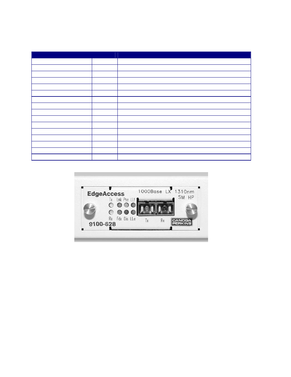
Figure 8. 9135G Interface LED Indicators
2.7.3 Enable/Disable LLF or LLE
You can select LLF and LLE or Remote Fault sensing in the hardware or software by specifying
hardware or software control for these functions in the user interface. For details on the user
interface, see Section 3.2.3, Port Information. LLF is limited to only one port at a time. To set these
functions on an interface module:
Step 1. Loosen the captive screws and pull the module out of the chassis.
Step 2. Locate SW1, then set it as needed:
• Switch position 1 controls LLF: On enables LLF; Off disables LLF
• Switch position 2 selects LLE or Remote Fault: On selects LLE; Off selects Remote Fault
Step 3. Insert the module in the chassis and tighten the captive screws.
Model 9135G SNMP Managed Gigabit Ethernet Switch
2-8