2 dc power entry, 2 dc power entry -3, Figure 3. typical dc power supply connections -3 – CANOGA PERKINS 9135G SNMP Managed Gigabit Ethernet Switch User Manual
Page 11
EdgeAccess Ethernet Switch
2.3.2 DC Power Entry
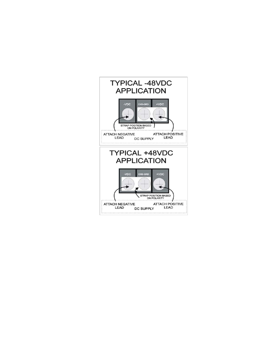
The connection for the -48VDC power supply is detailed in Figure 3.
-VDC
Terminal for negative lead
CHS-GND
Chassis ground terminal for DC supply
+VDC
Terminal for positive lead
Figure 3. Typical DC Power Supply Connections
The polarity of the source DC supply determines the position of the grounding strap on the 9135G
DC terminal strip.
For a -48VDC supply, connect the grounding strap between the Chassis Ground and the +VDC
terminal. Connect the positive (+), or Common, lead from the source DC supply to the +VDC
terminal, and connect the negative (-) lead from the source DC supply to the -VDC terminal.
For a +48VDC supply, connect the grounding strap between the Chassis Ground and the -VDC
terminal. Connect the negative (-), or Common lead, from the source DC supply to the -VDC
terminal, and connect the positive (+) lead from the source DC supply to the +VDC terminal.
Reversing the connections may cause damage to both the DC source and the DC converter module in
the 9135G.
Model 9135G SNMP Managed Gigabit Ethernet Switch
2-3