2 management access - modem slip connection, 3 fiber optic cabling, Connecting fiber optic cables – CANOGA PERKINS 9135G SNMP Managed Gigabit Ethernet Switch User Manual
Page 14: Cabling -6
EdgeAccess Ethernet Switch
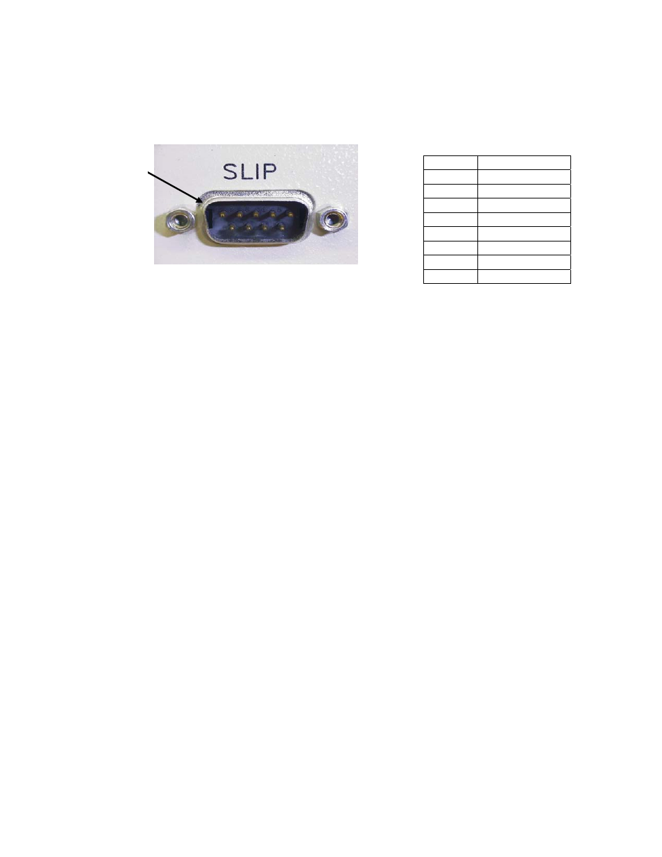
2.6.2 Management Access - Modem SLIP Connection
The SLIP Port, located on the rear panel of the 9135G, provides a modem connection to access the
management program.
Pin 1
DCD Input
Pin 2
RxD Input
Pin 3
TxD Output
Pin 4
DTR Output
Pin 5
SIG GND
Pin 6
DSR Input
Pin 7
RTS Output
Pin 8
CTS Input
Pin 9
Not Used
Pin 1
Figure 6. Modem SLIP Management Connection - SLIP
2.6.3 Fiber Optic Cabling
Connect all optical cables using Tx to Rx, and Rx to Tx orientation. Labeling each connector is highly
recommended. Keep optical connectors lint and dust free, clean, and protected when not in use.
Connecting Fiber Optic Cables
Dirty fiber connectors are a common source of attenuation, especially for single mode fiber. Keep the
connectors clean at all times and install the dust covers when not in use. Whenever there is a
significant, unexplained light loss, first clean the connectors. Use extreme care when removing or
installing connectors to avoid damaging the fiber end-face surface or the connector housing.
Caution! Clean the Fiber Connectors before connecting them. Dirt contaminates both the fiber
coupler and the fiber receptacle, and can cause a significant light signal loss.
Before installing any type of fiber cable or connector, use a lint-free alcohol pad from a fiber cleaning
kit to clean the ferrule and the end-face surface of the fiber coupler.
Use extreme care when installing or removing connectors to avoid damaging the fiber end-face
surface or the connector housing.
Model 9135G SNMP Managed Gigabit Ethernet Switch
2-6