3 display format – BendixKing KLN 900 - Pilots Guide User Manual
Page 36
3-9
Rev 2
3.3 DISPLAY FORMAT
The KLN 900 uses a Cathode Ray Tube (CRT) display.
The display screen is divided into segments. These seg-
ments are formed by horizontal and vertical lines on the
screen. Most of the time there are five segments as
shown in figure 3-28. There are occasionally times when
there are only four segments (figure 3-29) or one large
segment (figure 3-30).
Aeronautical information (also called “data”) is presented
on the screen in the form of “pages”. A page is a presen-
tation of specific data in an organized format. Various
page “types” are used to display related kinds of data.
For example, one page type is NAV (navigation). NAV
pages show information such as distance, groundspeed,
bearing, course, and other data relating to navigation.
Another page type is APT (airport). APT pages contain
information pertinent to a specific airport such as name,
location, elevation, runways, and communication frequen-
cies. There are numerous page types used to display the
KLN 900’s vast capabilities.
The units of measure for displayed information can be
changed using the SET 7 page. (Refer to section 5.3.1 for
details on this page.) The altimeter barometric setting can
be set to inches of mercury (“); millibars (mB), or
hectoPascals (hP). Altitude, airport elevation, and runway
lengths can be set to feet (ft) or meters (m). Finally, dis-
tances and velocities can be set to nautical miles (nm)
and knots (kt) or kilometers (km)and kilometers/hour
(k/h). Changing any of the units of measure only effects
the information displayed on the unit. It does not effect on
any of the data output by the unit. (Metric units for dis-
tance and speed are not provided by the ORS 01 soft-
ware.)
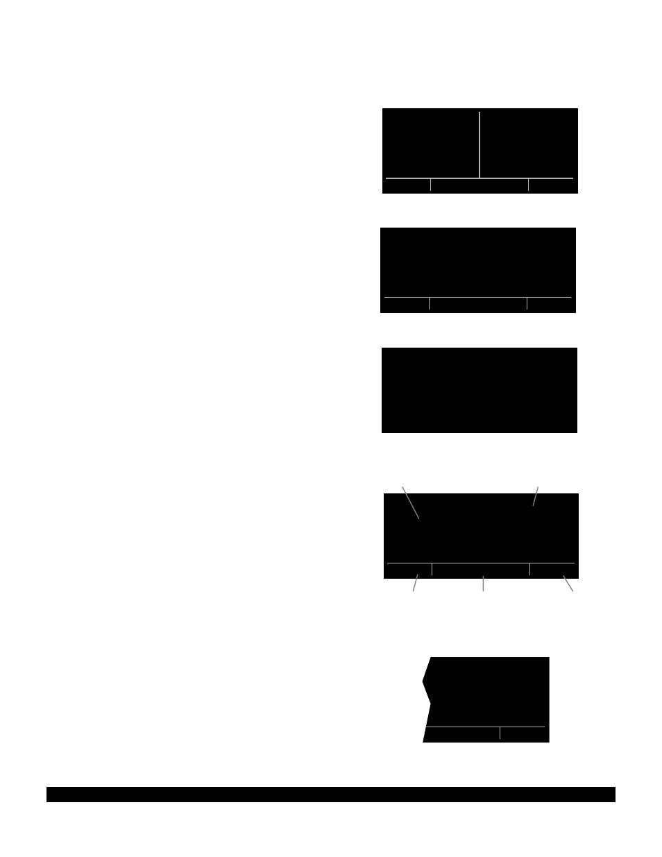
Normally, when the screen is divided into five segments,
the KLN 900 displays two pages at one time. These
pages are presented in the upper left and upper right seg-
ments of the screen. In figure 3-31 the upper left seg-
ment (A) is showing a Navigation page and the upper
right segment (B) is showing an Airport page. The lower
left segment (C) indicates which specific page is being
displayed on the left side. NAV 2 indicates that the
Navigation 2 page is being presented on the left side of
the screen. An Airport 4 page is being shown in the
upper right segment of the display (B) and is identified as
such with the APT 4 characters in the lower right segment
(D). The page identification includes a number appended
to the page type when there is more than one page for a
page type, such as in the two examples of pages shown
in figure 3-31. There is no number displayed in the page
identifier if there is only one page for a particular page
type. The VOR page identification in figure 3-32 shows
that there is only one VOR page.
| JAN D
|JACKSON
| H
|112.60 5^E
|N 32^30.44'
|W 90^10.05'
VOR
PRESENT POS|=KHIF
|CLR 124.10
OGD 122^fr|GRND 121.60
8.2nm|TWR 126.20
N 41^07.60'|APR 121.10
W111^58.30'|DEP 121.10
NAV 2 enr-leg
msg
APT 4
(A)
(B)
(C)
(E)
(D)
Figure 3-32
Figure 3-28
Figure 3-29
Figure 3-31
Figure 3-30