Verify the firing rate – Beckett CG4 User Manual
Page 20
20
Section: START THE BURNER
Call for Heat. Verify that burner fires up and the
gas valve closes. After control locks out, flame
shall go off.
6. Turn power off and reattach sensor wire. Turn
power back on. Control should reset. Initiate Call
for Heat.
7. After you have observed main flame for a brief time,
press the reset button on the control for 1 second
to shut down and re-start the burner. Monitor the
flame and safety shutoff valves to assure that
shutdown is controlled by the valves and that they
operate properly. With this test passed, you may
safely initiate automatic start-ups on subsequent
cycles.
8. While the burner is firing, examine the vent system
for evidence of leaks, obstructions, and for correct
function of the barometric draft control. Leak test
all gas piping from the burner to the utility supply
piping. If leaks are found, correct them immediately.
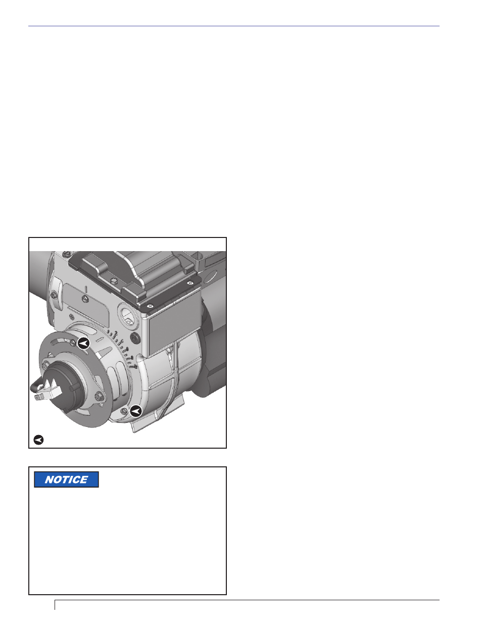
Figure 14 – Shutter and Band
= Tighten locking screws securely after adjustments have been made
The shutter and band both
control the amount of flow area
available for air inlet to the burner. The greater their
combined flow area, the higher the firing rate. The
primary differences between the two are their ease of
adjustment and their total airflow area. The shutter
turns more easily and has a smaller net flow area. As a
result we have found the shutter to be better suited for
low rate adjustments, and the band better suited for high
rate adjustments. We recommend that at low rates the
band be left completely closed until the shutter has been
fully opened, and that for higher rates the shutter is left
completely open as the band is opened.
Verify the Firing Rate
The primary method for verifying the burner’s firing
rate, for either natural gas or propane, is to assure that
the correct fuel orifice is properly installed and that the
gas valve outlet pressure is accurately set to 3.5” water
column.
1. Turn off electrical power to the burner and close the
main shutoff cock supplying gas to the burner.
2. Remove the plug from the outlet pressure tap on
the outlet end of the gas valve (
Figure 15) and
install a hose barb fitting and manometer.
3. Turn on system power and gas supply and initiate a
call for heat to light the burner.
4. The manometer should show 3.5” water column
pressure. If it does, turn off the burner and skip
ahead to step 6. If it doesn’t, let the burner continue
to run and adjust the gas valve pressure regulator
in the following steps.
5. Remove the regulator cover screw (see
Figure
15) from the regulator adjustment tower and turn
the regulator adjust screw clockwise to increase
pressure or counterclockwise to decrease pressure.
Set the regulator to produce a 3.5” water column
reading in the manometer. Check the appliance
breech or draft setting and adjust if necessary as it
can affect the setting. Replace the regulator cover
screw.
6. Turn off the burner and turn off all electrical power
to the system.
7. Remove the manometer hose and barb fitting from
the gas valve outlet pressure tap.
8. Replace the outlet pressure tap plug and tighten
(clockwise 40 – 60 in-lbs.).
9. Turn on system power and start the burner.
10. Check for leaks at the gas valve outlet pressure tap
plug using a leak detection solution or soapsuds.
Bubbles forming indicate a leak. SHUT OFF GAS
AND FIX ALL LEAKS IMMEDIATELY.
If the burner is firing natural gas it may be possible to
verify the firing rate by “clocking” the gas meter:
1. Locate the gas meter and examine its display
to be sure that you can determine a 1 cubic foot
usage of gas and that the meter is temperature
compensated.
2. Contact the gas utility to find the
heating value
of the gas. It can vary from about 950 BTU/Ft
3
to
about 1,100 BTU/Ft
3
.
3. Examine the gas piping to know of any other gas
appliances connected to it. Turn them off so that
only this burner is using gas from the meter.